
Molten aluminum filtration

a technology of aluminum filtration and aluminum slag, which is applied in the field of molten metal, can solve the problems of inconvenient method, high undesirable molten salt, and undesirable halides

Inactive Publication Date: 2005-08-04
ECKERT C EDWARD
View PDF4 Cites 20 Cited by
  • Summary
  • Abstract
  • Description
  • Claims
  • Application Information

AI Technical Summary

Benefits of technology

[0011] And yet a further object of the invention is to provide an improved process for a body of molten aluminum wherein the fluxing gas is finely dispersed throughout the body for improved contact of fluxing gas with metal.
[0012] Still, yet another object of the invention is to provide a process for providing increased shear forces in a body of molten metal for improved dispersion of treatment media, such as fluxing gases and salts, throughout the body.
[0013] And still a further object of this invention is to provide a process for fluxing molten aluminum wherein large amounts of fluxing gas can be added without entrainment or fuming above the melt.

Problems solved by technology

These halides are undesirable because they contribute significantly to process airborne emissions.
Molten salts are highly undesirable because of the difficulty of removing to the surface for skimming.
However, this method is not without limitations.
The increased exposure of the molten metal to air results in an increase in dross formation, subsequent entrainment of the dross and its detrimental collateral effects.
When the fluxing material is a gas, the vortex creates a problem in yet another way.
Fluxing gas is displaced towards the center of the vortex by body force separation with the result that other parts of the molten body are not adequately treated with fluxing gas.
Thus, the effectiveness of the process is reduced because portions of the molten body do not get treated with fluxing material.
In addition, fluxing gas entrained in the molten metal flow pattern tends to coalesce, resulting in larger bubbles of fluxing gas developing in the melt.
The larger bubbles lower the effectiveness of the fluxing process because less molten metal gets treated.
However, baffles are undesirable because a dead volume develops behind the trailing edges of the baffle.
However, this severely limits efficiency.
These problems continue to plague the industry as indicated in U.S. Pat. No. 5,160,693, for example, which discloses that with rotating impellers a surface vortex forms, the vortex rotating about and flowing downwardly along the impeller shaft, thereby agitating surface dross and drawing impurities back into the melt.

Method used


Image

  • Molten aluminum filtration
  • Molten aluminum filtration
  • Molten aluminum filtration

Examples


example

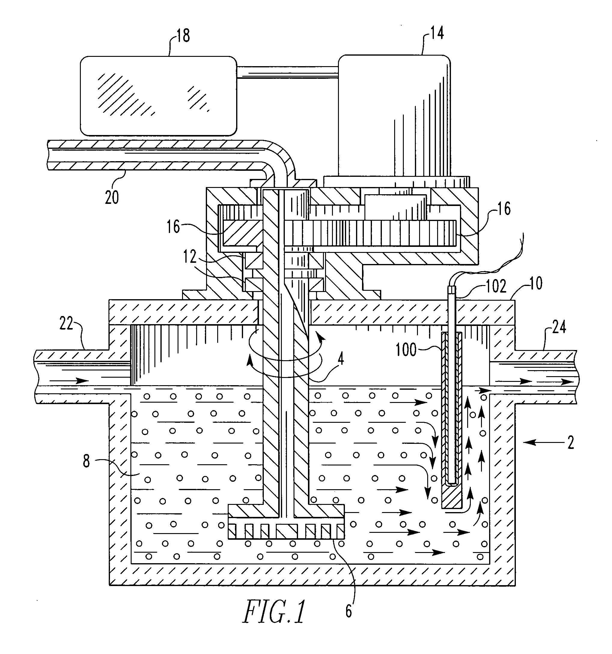
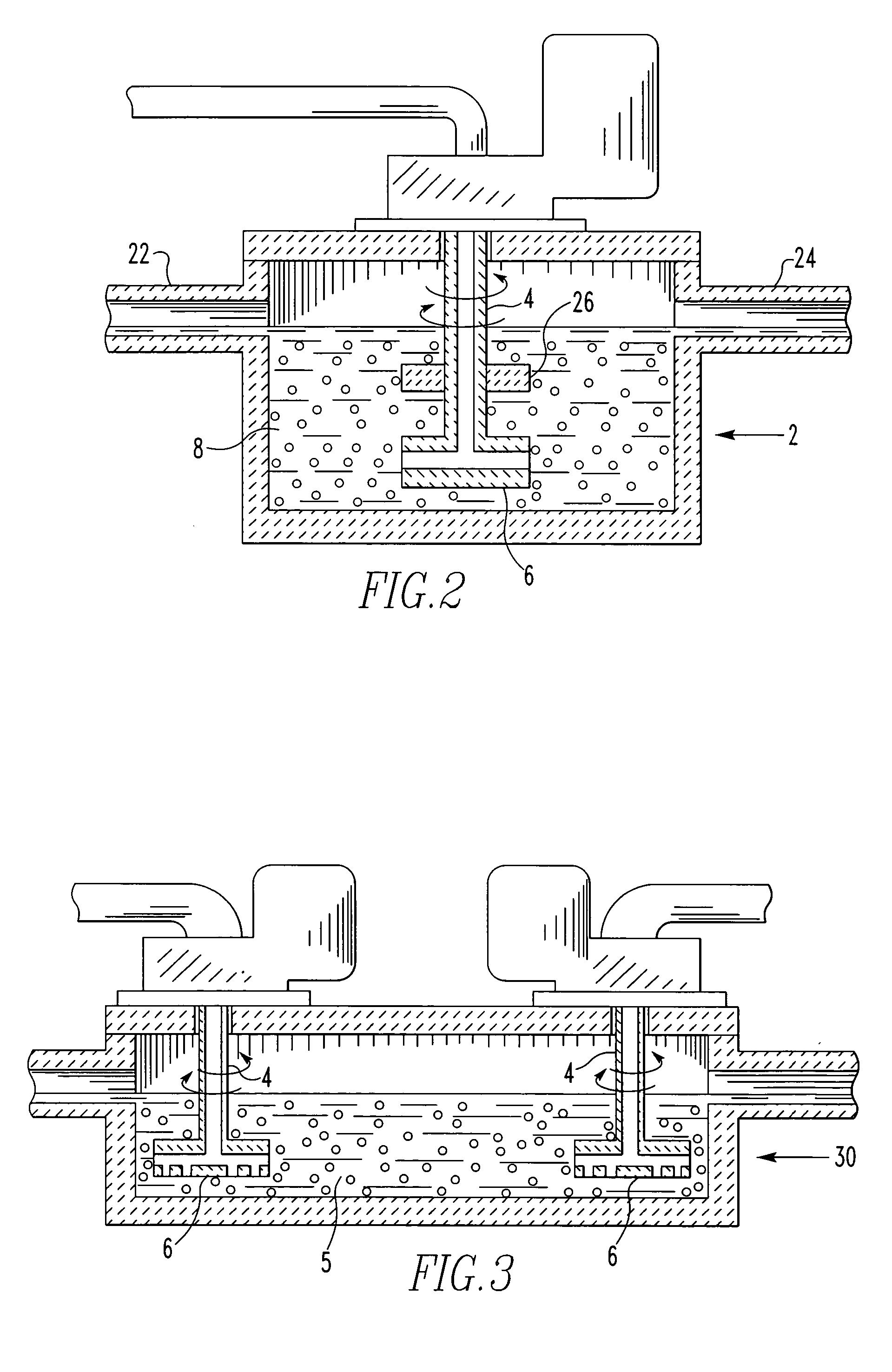
[0100] For purposes of demonstrating the effectiveness of reverse rotation for purposes of fluxing molten aluminum on a continuous basis, a chamber containing molten aluminum was used and an impeller having an 8 inch diameter was immersed in the molten aluminum to a depth of 25 inches. The chamber had a circular cross-section. The impeller was rotated at a speed of 425 RPM and the direction of rotation was reversed every 24 seconds. Molten aluminum was flowed through the chamber at a rate of 61,000 lbs / hour and the metal residence time in the chamber was 97 seconds. For purposes of hydrogen removal, argon gas was introduced through the impeller at a rate of 150 SCF / hour. Hydrogen concentration is given in cm.sup.3H2 (STP) / 100 g Al and determined by Ransley solid extraction method. Aluminum alloys AA6111 and AA3004 were tested. The results are as follows:

TABLE IAlloyUpstream H2Downstream H2% SampleConcentrationConcentrationReduction6111-10.230.0961%6111-20.240.0963%6111-30.260.0965...


PUM

PropertyMeasurementUnit
temperaturesaaaaaaaaaa
median particle sizeaaaaaaaaaa
particle sizesaaaaaaaaaa

Abstract

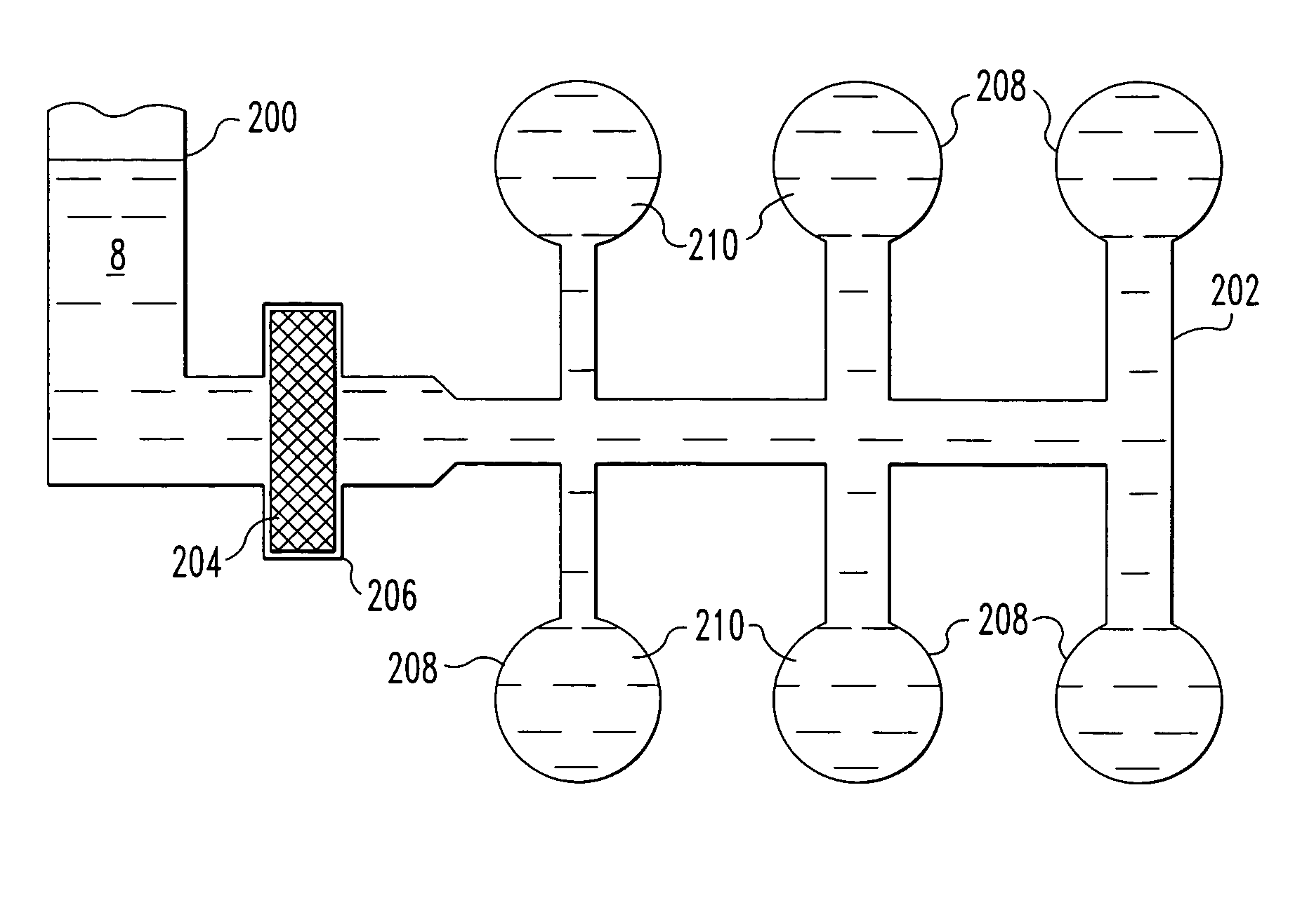
A filter material for molten aluminum, the material subsequently dissolvable in molten aluminum to recover aluminum captured therein.

Description

BACKGROUND OF THE INVENTION [0001] This invention relates to molten metal such as molten aluminum, and more particularly, it relates to an improved method for filtering molten metals such as molten aluminum to provide improved quality metal. [0002] The use of a chlorine containing reactive fluxing gas, for the purpose of removing alkali elements (i.e., Na, Ca, K, Li), is a well established practice in the treatment of molten aluminum. Under equilibrium conditions, the respective chlorides of these elements are produced as reaction products. With the exception of LiCl, all of these halide salts, as pure species, are solid at normal treatment temperatures and thus are easily separated to the melt surface as a supemate and are removed by skimming. [0003] Alkali elements are usually present at melt concentrations less than 500 ppm. According to the law of mass action (reaction rate approximately proportional to the concentration of reacting species), non-equilibrium metastable salts suc...

Claims


Application Information

Patent Timeline
Patent Type & Authority Applications(United States)
IPC IPC(8): B22C9/08
CPCB22C9/086
Inventor ECKERT, C. EDWARD
Owner ECKERT C EDWARD
Learn More