
Slag retaining ring for cast iron quantitative seat bag pouring and preparation method thereof

A slag retaining ring and seat bag technology, which is applied in casting equipment, manufacturing tools, metal processing equipment, etc., can solve the problems of weakening the buoyancy of molten iron upward, reducing the working life of the slag retaining ring, and the slag retaining ring cannot float up in time, etc. To achieve the possible effect of improving the buoyancy, improving the slag blocking effect and reducing the brokenness

Active Publication Date: 2016-01-20
HUDONG HEAVY MACHINERY
View PDF6 Cites 0 Cited by
  • Summary
  • Abstract
  • Description
  • Claims
  • Application Information

AI Technical Summary

Problems solved by technology

[0003] The existing slag retaining ring is generally a ring with a square cross section, please refer to figure 1 , which has two defects: one is that the force of the molten iron on the side of the square section is in the horizontal direction (see figure 1 (indicated by the middle arrow), this force will weaken the buoyancy of molten iron on the bottom surface of the square section, so the buoyancy of the slag retaining ring with this structural shape is poor, and some slag retaining rings cannot float up in time, thus affecting the slag retaining effect; , the side and bottom of the square section form sharp edges and corners, and the local strength is greatly weakened, which makes the slag retaining ring easy to break. into the mold, resulting in defects in the casting
In addition, the existing slag retaining rings are all processed from a whole piece of graphite. Although the slag retaining effect is good, the price is expensive, which increases the production cost of the enterprise.

Method used


Image

  • Slag retaining ring for cast iron quantitative seat bag pouring and preparation method thereof
  • Slag retaining ring for cast iron quantitative seat bag pouring and preparation method thereof
  • Slag retaining ring for cast iron quantitative seat bag pouring and preparation method thereof

Examples


Embodiment Construction

[0027] The invention provides a slag retaining ring in a slag retaining mechanism when pouring large iron castings with a quantitative seat ladle. It can effectively prevent the scum on the surface of the molten iron in the seat bag from entering the mold.

[0028] The present invention will be further described below in conjunction with the accompanying drawings and specific embodiments, but the protection scope of the present invention should not be limited thereby.

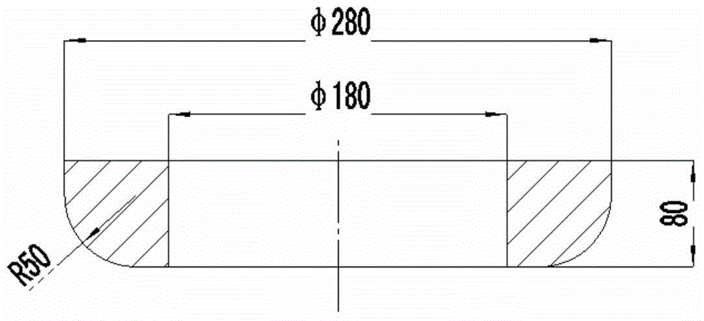
[0029] Please see first figure 2 , as shown in the figure, the slag retaining ring for pouring cast iron quantitative seat bag is a torus, and the lower peripheral part of the section passing through the central axis of the torus is arc-shaped. In other words, the lower part of the torus-shaped slag retaining ring The cross-section of the outer circumference is arc-shaped; the resultant force of the molten iron buoyancy on the lower outer circumference points to the central axis above the torus, see image 3...


PUM

PropertyMeasurementUnit
radiusaaaaaaaaaa
thicknessaaaaaaaaaa

Abstract

The invention discloses a slag retaining ring for cast iron quantitative receiving ladle casting and a production method thereof. The slag retaining ring comprises a ring body. The lower outer circumference of the cross section of the ring body penetrating a central axis is in an arc shape, and the resultant force of the lower outer circumference applied by iron buoyancy points to the central axis above the ring body. The slag retaining ring is made of casting quartz modeling sand. The invention further provides a production method of the slag retaining ring adopting the quartz modeling sand as raw material. By the aid of the slag retaining ring and the production method, floating performance is improved, production cost is reduced, strength is improved, slag retaining effect is improved, service life and cast quality are guaranteed, and the slag retaining ring and the production method are adaptable to quantitative receiving ladle casting of large scale cast iron pieces.

Description

technical field [0001] The invention relates to a process equipment for metal casting, in particular to a slag retaining ring for pouring cast iron quantitative seat ladle and a preparation method thereof, belonging to the technical field of casting. Background technique [0002] In order to prevent impurities such as molten iron slag and molten iron oxidized slag from entering the mold and affecting the quality of castings, many foundries currently use quantitative pouring seats when pouring large iron castings, and install plugs on the quantitative seats. Slag blocking mechanism. In the later stage of casting casting, the molten iron will form a vortex above the nozzle of the seat bag. When the molten iron in the seat bag has a certain height, the vortex will involve the scum on the surface of the molten iron and bring it into the cavity, which will eventually cause slag inclusions in the casting. Defects. In order to improve the slag blocking effect, a slag blocking rin...

Claims


Application Information

Patent Timeline
Patent Type & Authority Patents(China)
IPC IPC(8): B22D41/00
Inventor 陶卫生高永健江敏金志宏
Owner HUDONG HEAVY MACHINERY
Learn More