Grouting equipment used for manufacturing of cement prefabricated components

A cement prefabricated part and grouting technology, which is applied in the direction of manufacturing tools, ceramic molding machines, etc., can solve the problems of long grouting time, low work efficiency, and long intermittent time, and achieve simple piston movement structure and fast grouting intermittent time. Short, continuous effect of piston movement

Inactive Publication Date: 2019-05-03
广州全系新材料股份有限公司
View PDF0 Cites 0 Cited by
  • Summary
  • Abstract
  • Description
  • Claims
  • Application Information

AI Technical Summary

Problems solved by technology

[0002] Cement prefabricated parts are cement parts that are made of cement and steel cages with molds and then installed. In the process of cement prefabricated parts, grouting equipment is needed. Because cement prefabricated parts are mass-produced, the grouting equipment needs It is convenient to move. The existing grouting equipment includes hydraulic grouting machine, extrusion grouting machine, screw type grouting machine and piston type grouting machine. The hydraulic grouting machine is large in size and is not suitable for prefabricated parts. Squeeze grouting machines are easy to damage and are not suitable for batch grouting. Screw type grouting machines are mainly used in building construction and are not suitable for prefabricated parts grouting due to their large volume. However, the existing piston type grouting machines are The intermittent time is relatively long, resulting in long grouting time, low work efficiency, and the piston movement structure is complicated, and maintenance is troublesome when damaged

Method used


Image

  • Grouting equipment used for manufacturing of cement prefabricated components
  • Grouting equipment used for manufacturing of cement prefabricated components
  • Grouting equipment used for manufacturing of cement prefabricated components

Examples


Embodiment 1

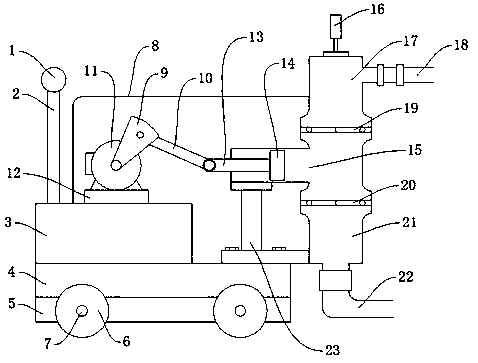
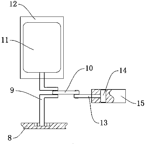
[0037] Such as Figure 1-Figure 3 As shown, a grouting equipment for processing cement prefabricated parts, including a wheel 6, a chassis 3, a motor 11, and a chassis 4, a rotating shaft 7 is arranged in the middle of the wheel 6, and the rotating shaft 7 is used to place the wheel 6 and allow the wheel 6 to rotate. A wheel frame 5 is arranged behind the wheel 6, and the wheel frame 5 is used to place the rotating shaft 7. A chassis 4 is arranged on the wheel frame 5, and the chassis 4 is used for stabilizing the supporting equipment. A chassis 3 is arranged on the chassis 4, and a base is arranged on the chassis 3. 12. The base 12 is used to place the motor 11. The motor 11 is arranged on the base 12. The motor 11 is used to provide power. The side of the motor 11 is provided with a bracket 2. The bracket 2 is used to place the armrest 1. The armrest 1 is arranged on the bracket 2. Handrail 1 is used for pushing, and crankshaft 9 is arranged in front of motor 11, and cranksh...

Embodiment 2

[0039]A grouting equipment for processing cement prefabricated parts, including a wheel 6, a chassis 3, a motor 11, and a chassis 4. A rotating shaft 7 is arranged in the middle of the wheel 6. The rotating shaft 7 is used to place the wheel 6 and allow the wheel 6 to rotate. A wheel frame 5 is provided, and the wheel frame 5 is used to place the rotating shaft 7. The wheel frame 5 is provided with a chassis 4, and the chassis 4 is used for stabilizing the supporting equipment. The chassis 4 is provided with a chassis 3, and the chassis 3 is provided with a base 12. 12 is used to place the motor 11, the base 12 is provided with the motor 11, the motor 11 is used to provide power, the side of the motor 11 is provided with a bracket 2, the bracket 2 is used to place the armrest 1, and the armrest 1 is arranged on the bracket 2, and the armrest 1 is used For pushing, the front of the motor 11 is provided with a crankshaft 9, the crankshaft 9 is used to drive the rocker 10 to rotat...

Embodiment 3

[0041] A grouting equipment for processing cement prefabricated parts, including a wheel 6, a chassis 3, a motor 11, and a chassis 4. A rotating shaft 7 is arranged in the middle of the wheel 6. The rotating shaft 7 is used to place the wheel 6 and allow the wheel 6 to rotate. A wheel frame 5 is provided, and the wheel frame 5 is used to place the rotating shaft 7. The wheel frame 5 is provided with a chassis 4, and the chassis 4 is used for stabilizing the supporting equipment. The chassis 4 is provided with a chassis 3, and the chassis 3 is provided with a base 12. 12 is used to place the motor 11, the base 12 is provided with the motor 11, the motor 11 is used to provide power, the side of the motor 11 is provided with a bracket 2, the bracket 2 is used to place the armrest 1, and the armrest 1 is arranged on the bracket 2, and the armrest 1 is used For pushing, the front of the motor 11 is provided with a crankshaft 9, the crankshaft 9 is used to drive the rocker 10 to rota...


PUM


Abstract

The invention discloses grouting equipment used for manufacturing of cement prefabricated components. The grouting equipment comprises wheels, an engine case, a motor and a chassis; driving shafts arearranged between the wheels; the rear sides of the wheels are provided with a wheel rack; the chassis is arranged on the wheel rack; the engine case is arranged on the chassis; the base is arranged on the engine case; the motor is arranged on the base; a support is arranged on one side of the motor; a handle is arranged on the support; a crank is arranged on the front side of the motor; a rockingrod is arranged on one side of the crank; a piston rod is arranged on one side of the rocking rod; a piston is arranged on one side of the piston rod; a piston material cylinder is arranged on the outer side of the piston; and a protection cover is arranged on the piston material cylinder. The grouting equipment has the beneficial effects that a connection rod mechanism is adopted, and the pistonmoving structure is simple, so that design is reasonable; piston movement is continuous, and reciprocating movement is rapid, so that the intermittent time for grouting is extremely short; and the working efficiency is high.

Description

technical field [0001] The invention relates to the field of cement prefabricated parts, in particular to a grouting equipment for processing cement prefabricated parts. Background technique [0002] Cement prefabricated parts are cement parts that are made of cement and steel cages with molds and then installed. In the process of cement prefabricated parts, grouting equipment is needed. Because cement prefabricated parts are mass-produced, the grouting equipment needs It is convenient to move. The existing grouting equipment includes hydraulic grouting machine, extrusion grouting machine, screw type grouting machine and piston type grouting machine. The hydraulic grouting machine is large in size and is not suitable for prefabricated parts. Squeeze grouting machines are easy to damage and are not suitable for batch grouting. Screw type grouting machines are mainly used in building construction and are not suitable for prefabricated parts grouting due to their large volume. ...

Claims


Application Information

Patent Timeline
Patent Type & Authority Applications(China)
IPC IPC(8): B28B1/26
Inventor 王文华
Owner 广州全系新材料股份有限公司
Why Eureka
Try Eureka