Buoyant device for amphibious operation drilling platform

A technology of drilling platform and buoyancy device, which is applied in the fields of petroleum engineering drilling and basic engineering drilling to achieve the effect of improving stability

Active Publication Date: 2019-05-03
SOUTHWEST PETROLEUM UNIV
View PDF6 Cites 4 Cited by
  • Summary
  • Abstract
  • Description
  • Claims
  • Application Information

AI Technical Summary

Problems solved by technology

However, when the drilling platform is switching the operating environment, the amphibious drilling platform generally has a relatively large weight, and the buoyancy generated by the drilling platform itself on the water surface is not enough to support its stable floating.

Method used


Image

  • Buoyant device for amphibious operation drilling platform
  • Buoyant device for amphibious operation drilling platform
  • Buoyant device for amphibious operation drilling platform

Examples


Embodiment 1

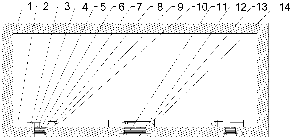
[0024] Such as Figure 1~3 As shown, this embodiment includes two airbags I6 and one airbag II11, a rectangular groove I5 is respectively opened on both sides of the bottom of the base 1, and a rectangular groove II12 is opened in the middle of the bottom surface of the base 1, and the airbag I6 is in the form of Folded and placed in the rectangular groove Ⅰ5, the airbag II11 is folded and placed in the rectangular groove II12, there are three inflation mechanisms inside the base 1, the inflation mechanism includes the fan 2, the booster pump 3 and the air pipe 4, the booster The pump 3 is arranged on the trachea 4, and one end of the trachea 4 communicates with the air outlet of the fan 2, and the other end of the trachea 4 passes through the base 1 and then communicates with the airbag I6; the airbag I6 is U-shaped after inflation and expansion, and the airbag I6 The inner vertical section of the airbag I6 is placed in the rectangular groove I5, the distance between the side...

Embodiment 2

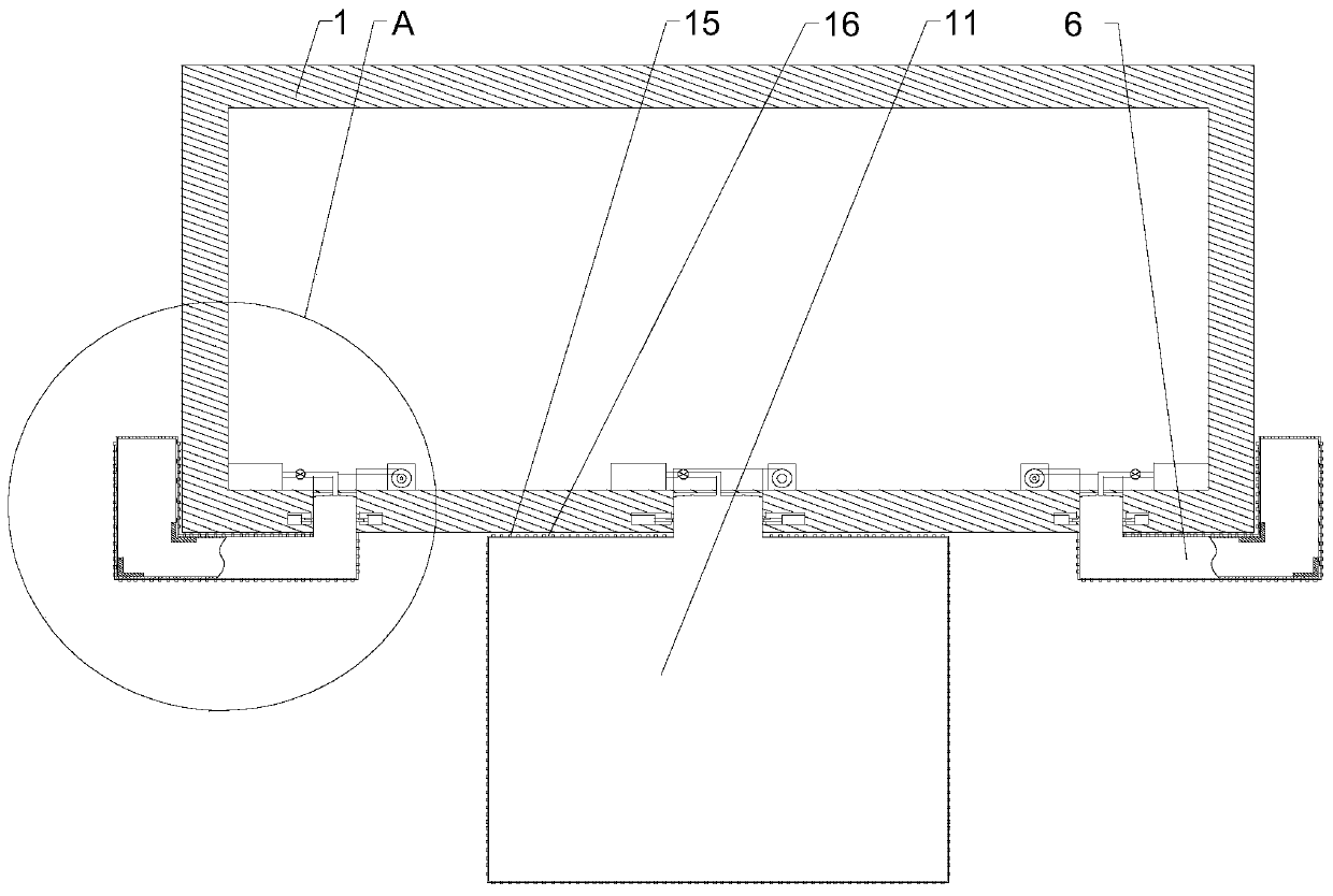
[0030] Such as Figure 1~3 As shown, this embodiment is based on Embodiment 1. When the initial state or the drilling process is completed, the airbag I6 and the airbag II11 will be folded in the rectangular groove I5 and the rectangular groove II12 respectively. When the airbag II11 is used, the airbag I6 or the airbag II11 cannot be completely accommodated in the groove only by the draft of the fan 2. For this, the applicant has provided a plurality of hanging rings I19 on the outer surface of the airbag I6, and on the outer surface of the airbag II11 There are multiple hanging rings II15 on the top, and because the airbag I6 is inflated and expanded, it is U-shaped, and the multiple hanging rings I19 located on the inner surface of the airbag I6 are connected in series with the winding roller in the base 1 through a traction rope I20 The multiple hanging rings I19 on the outer surface of the airbag I6 are connected in series with the winding roller II10 in the base 1 throug...

Embodiment 3

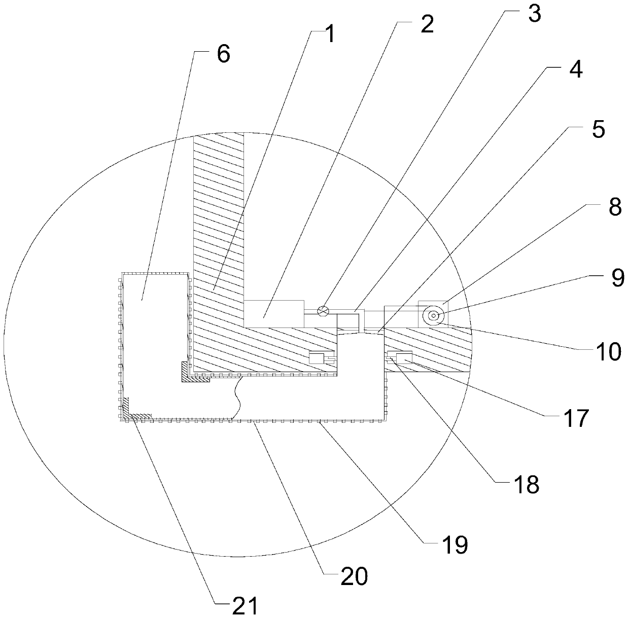
[0033] Such as Figure 1~3 As shown, this embodiment is based on Embodiment 2, because the drilling platform often switches between the land environment and the water environment, the rectangular groove I5 and the rectangular groove II12 may have wading situations, and long-term immersion will Corrosion of the airbag I6 or the airbag II11, adhesion of microorganisms, etc., can easily reduce the service life of the airbag. For this, the applicant has two opposite sides on the inner side walls of the rectangular groove I5 and the rectangular groove II12. The provided cavity is provided with a driving cylinder 17, a rectangular through hole communicating with the rectangular groove I5 or rectangular groove II12 is opened on the cavity wall, and a sealing plate 7 is provided on the output end of the driving cylinder 17, After the airbag is recovered, the driving cylinder 17 can be activated until the opposite end surfaces of the two sealing plates 7 contact each other, so as to cl...


PUM


Abstract

The invention discloses a buoyant device for an amphibious operation drilling platform. The buoyant device includes two air bags I and one air bag II, wherein two sides of the bottom of a substrate are each equipped with one rectangular groove I; a rectangular groove II is formed in the middle part of the bottom surface of the substrate; the air bags I are folded and are arranged in the rectangular groove I; the air bag II is folded and is arranged in the rectangular groove II; three inflation mechanisms are arranged in the substrate; a booster pump is arranged on an air pipe; one end of the air pipe is communicated with an air outlet of a blower fan, and the other end of the air pipe penetrates through the substrate and then is communicated with the corresponding air bag I; the expanded air bags I after inflation are U-shaped; the expanded air bag II after inflation is T-shaped; and on the premise that when the buoyancy force generated by substrate when the substrate is immersed in the water is insufficient to ensure the floating state of the substrate can be maintained, the buoyant device which acts as an auxiliary buoyancy lifting device for the drilling platform to move on thewater surface, can supplement the lacked buoyancy force of the substrate and the operation platform through full expansion of the air bags I and the air bag II, and can ensure that the substrate can float on the water like a ship.

Description

technical field [0001] The invention relates to the fields of basic engineering drilling, petroleum engineering drilling, etc., in particular to a buoyancy device for amphibious drilling platforms. Background technique [0002] The scale of modern engineering construction continues to expand, and a large number of large-scale engineering projects such as super high-rise buildings and long-span bridges have appeared, and the pile foundations supporting these giants are their most important foundation. Reverse circulation drilling rigs are used in large-diameter ultra-deep pile foundations of large buildings on land, complex strata such as hard rock formations, pile foundation construction of ports and wharves, embankment protection pile construction, and bridge pile foundation construction in rivers, lakes, and seas. However, for areas with relatively special geological conditions, such as soft soil areas - lacustrine floodplains, marine deltas, and shallow water tidal flats ...

Claims


Application Information

Patent Timeline
Patent Type & Authority Applications(China)
IPC IPC(8): B63B35/44
Inventor 郭亮裴春郭辉魏蒙钱德良刘壮志张军伟曲宏略徐凯
Owner SOUTHWEST PETROLEUM UNIV
Why Eureka
Try Eureka