
Automatic arranging and feeding device for firework cylinders

An automatic arrangement and automatic feeding technology, applied in the direction of conveyor control devices, transportation and packaging, conveyors, etc., can solve the problems of slow feeding speed, rising cost, laborious and laborious, etc., to ensure production speed and output, The effect of improving production efficiency and shortening the ascent distance

Pending Publication Date: 2019-05-03
广州胜美智能设备有限公司
View PDF10 Cites 5 Cited by
  • Summary
  • Abstract
  • Description
  • Claims
  • Application Information

AI Technical Summary

Problems solved by technology

[0002] During the production of rubber cartridges, a cutting machine is often used for cutting and processing. However, in the feeding process of the rubber cartridges of the cutting machine, it is still limited to manually placing the rubber cartridges one by one on the inclined plate of the discharge mold before loading. , the way of manual feeding is not only labor-intensive, the feeding speed is slow and the cost is high, resulting in low production efficiency of the rubber cartridge, and the rubber cartridge will also fall when the rubber cartridge is rolling down; especially Today's young people are generally unwilling to do jobs with relatively high labor intensity, and older workers are gradually retiring, making it difficult to recruit workers, which further exacerbates the rise in costs

Method used


Image

  • Automatic arranging and feeding device for firework cylinders
  • Automatic arranging and feeding device for firework cylinders
  • Automatic arranging and feeding device for firework cylinders

Examples


Embodiment

[0032] Such as Figure 10 As shown, the rubber cartridge 10 includes a barrel body 101 and nozzles 102 provided at both ends of the barrel body, and a circular waist groove 103 is provided in the middle of the barrel body.

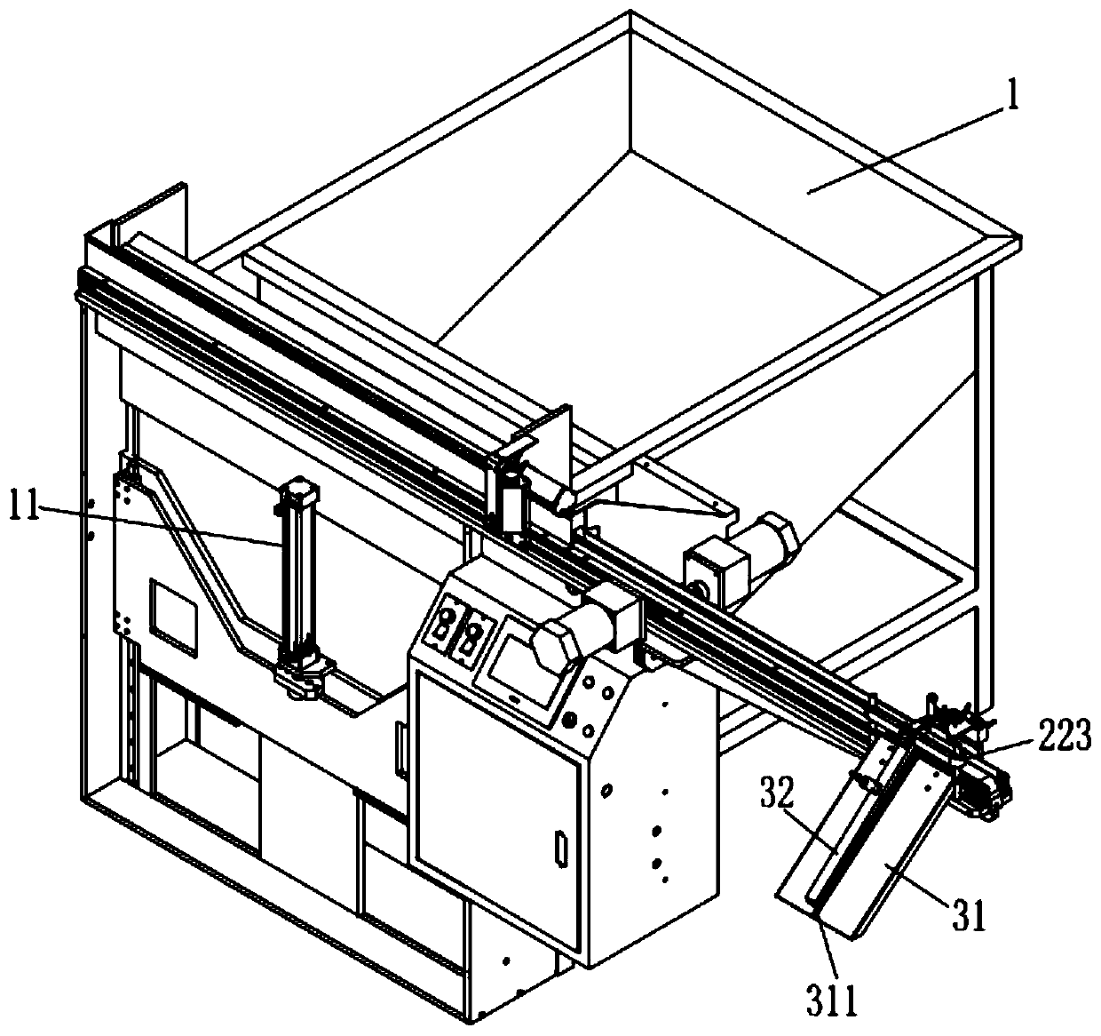
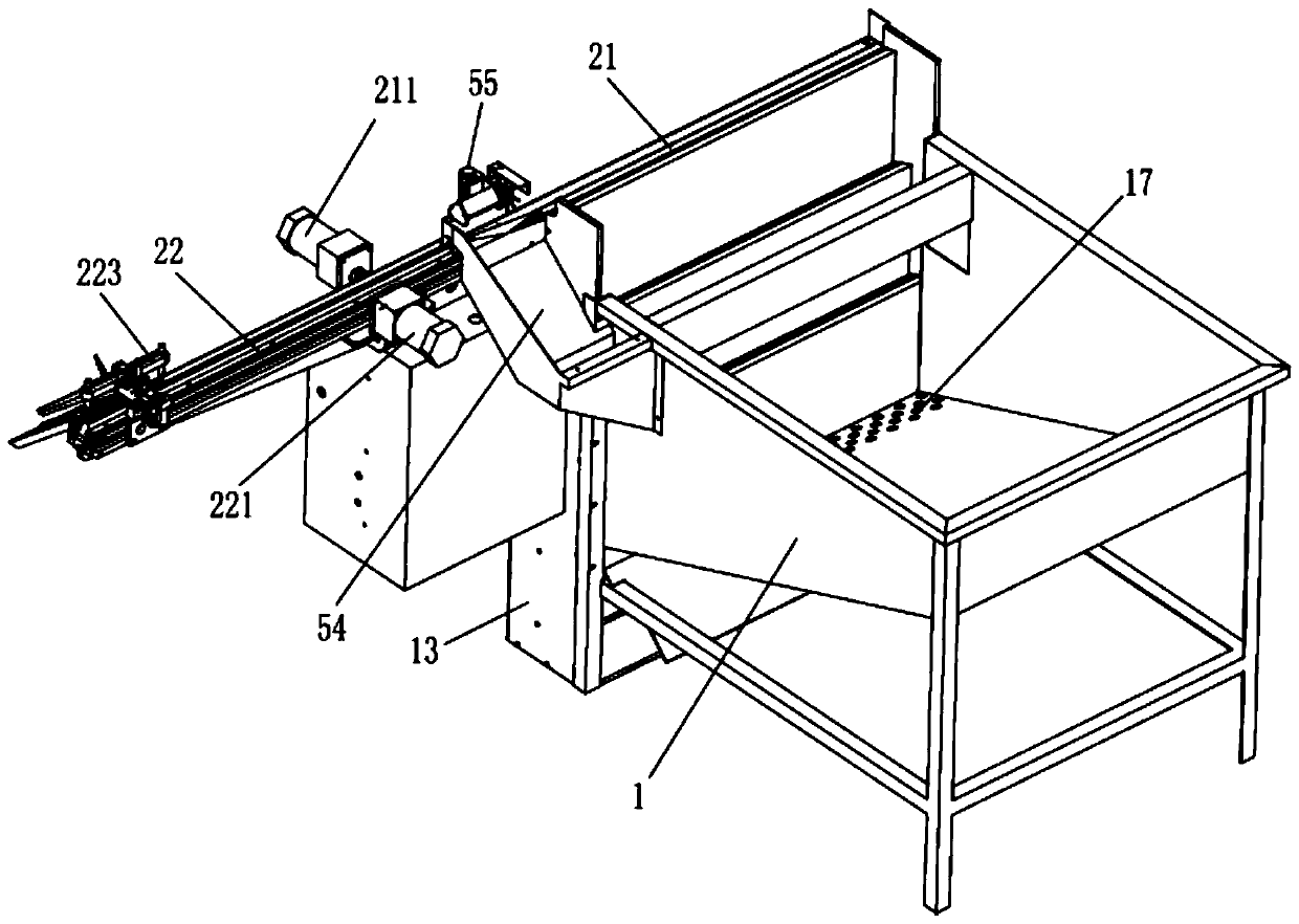
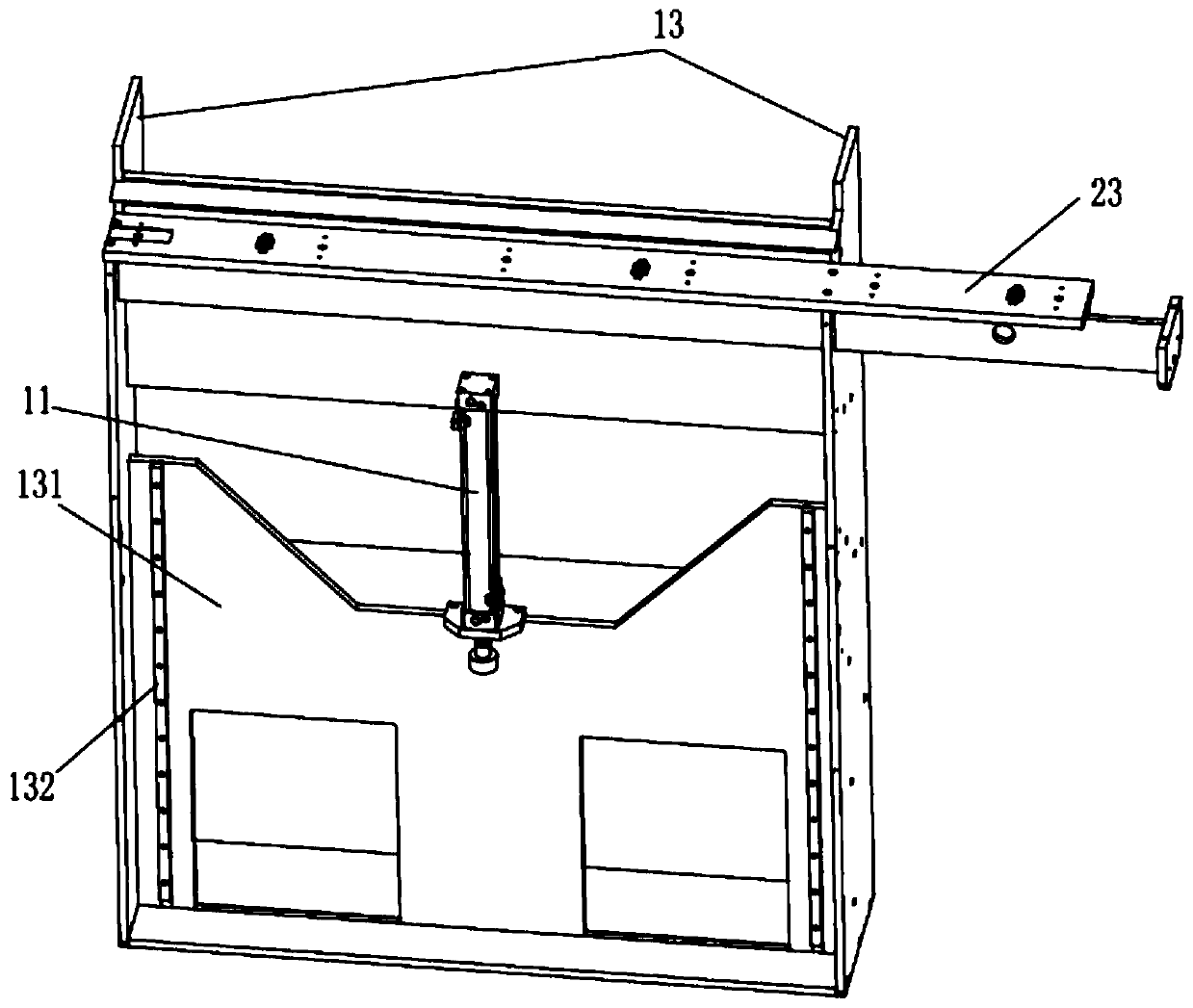
[0033] Such as Figure 2 to Figure 12As shown, the automatic arrangement and feeding device for fireworks tubes shown in this embodiment is used for automatic loading and arrangement and unloading of rubber tubes, and specifically includes an automatic feeding mechanism, a transmission mechanism and an arrangement and unloading mechanism. The automatic feeding mechanism includes The hopper 1 and the lifting part arranged at one end of the hopper 1, the lifting part includes a bracket connected to one end of the hopper 1, a first cylinder 11 vertically arranged on the bracket, and an upper cylinder connected vertically with the piston rod of the first cylinder 11. Material push pedal 12, the feeding push pedal 12 is positioned at an end of the hopper 1; T...


PUM


Abstract

The invention discloses an automatic arranging and feeding device for firework cylinders. The automatic arranging and feeding device for the firework cylinders comprises an automatic feeding mechanism, a conveying mechanism and an arranging blanking mechanism. The automatic feeding mechanism comprises a hopper and a lifting portion arranged at one end of the hopper. The lifting portion comprises asupport connected with one end of the hopper, a first cylinder arranged on the support and feeding push plates connected with the first cylinder. The feeding push plates are located inside one end ofthe hopper. The conveying mechanism comprises a conveying belt arranged at the upper end of the support and a motor which is in transmission connection with the conveying belt. The top ends of the feeding push plates are inclined planes inclined to the conveying belt. The arranging blanking mechanism comprises a discharging mold lower inclined plate and a discharging mold upper inclined plate arranged above the discharging mold lower inclined plate. A flowing channel for downward flowing of rubber cylinders is formed between the discharging mold lower inclined plate and the discharging mold upper inclined plate. First blowing nozzles for horizontal blowing are arranged in positions, corresponding to the position of the discharging mold lower inclined plate, in the conveying belt. By meansof the automatic arranging and feeding device for the firework cylinders, the purposes of automatic feeding conveying and arranging blanking can be achieved; in addition, the feeding speed is improved, and the cost is lowered; and production efficiency is improved.

Description

technical field [0001] The invention belongs to the technical field of rubber tube feeding, and in particular relates to an automatic arrangement and feeding device for fireworks tubes. Background technique [0002] During the production of rubber cartridges, a cutting machine is often used for cutting and processing. However, in the feeding process of the rubber cartridges of the cutting machine, it is still limited to manually placing the rubber cartridges one by one on the inclined plate of the discharge mold before loading. , the way of manual feeding is not only labor-intensive, the feeding speed is slow and the cost is high, resulting in low production efficiency of the rubber cartridge, and the rubber cartridge will also fall when the rubber cartridge is rolling down; especially Today's young people are generally unwilling to do more labor-intensive jobs, and older workers are gradually retiring, making it difficult to recruit workers, which further exacerbates the ri...

Claims


Application Information

Patent Timeline
Patent Type & Authority Applications(China)
IPC IPC(8): B65G47/14B65G43/08B65G15/22B65G23/22B65G47/256
Inventor 李三土左泽洲
Owner 广州胜美智能设备有限公司
Learn More