A simulated ice brick and an ice slideway
A technology of ice blocks and slides, which is applied to roads, water skiing, roads, etc., can solve the problems of inability to promote and use in a large area, high temperature requirements, and small use areas, and achieves convenient construction, crystal clear color, and rapid construction. Effect
- Summary
- Abstract
- Description
- Claims
- Application Information
AI Technical Summary
Problems solved by technology
Method used
Image

Examples
Embodiment 1
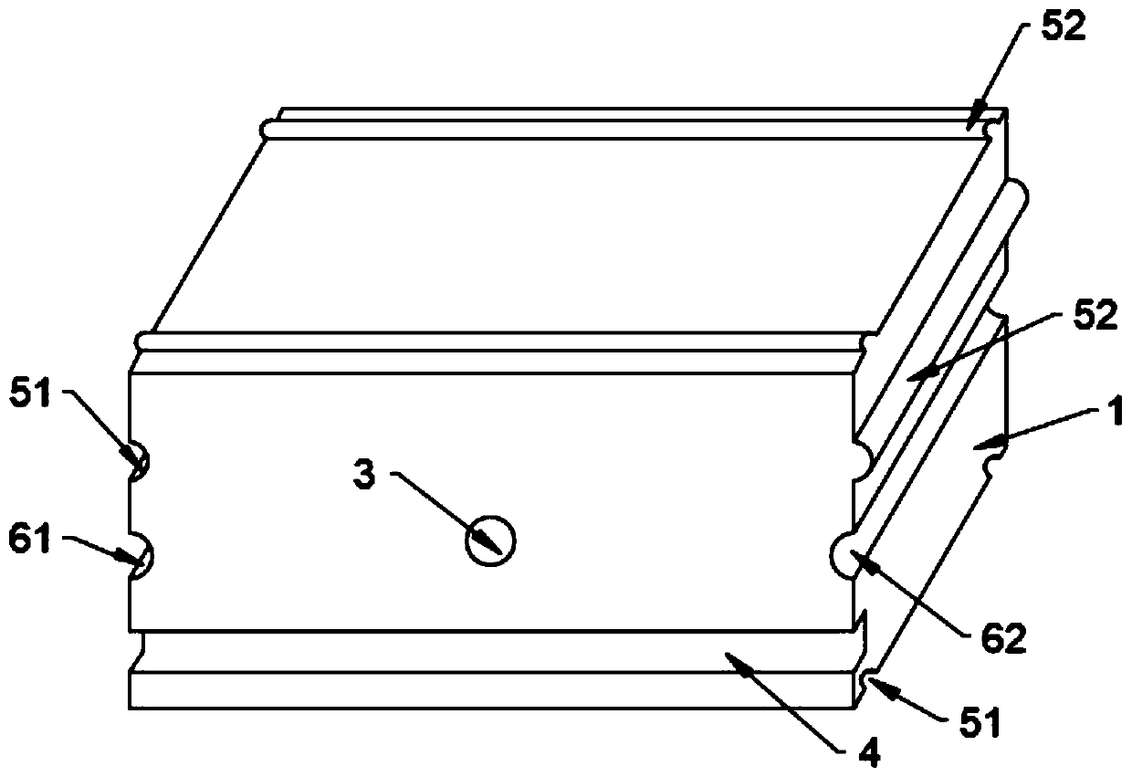
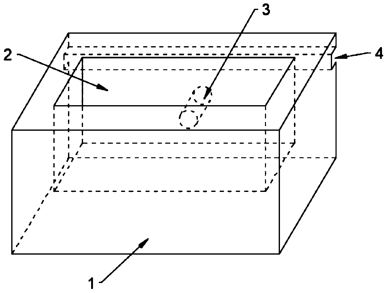
[0031] Such as Figure 1-2 As shown, a simulated ice brick has an ice brick body 1, the ice brick body 1 is a hollow structure, and the bottom of the ice brick body 1 is provided with an opening 2 communicating with the outside world; A spray hole 3 communicating with the hollow structure is provided on the side, and a spray device or a spray pipeline is set in the hollow structure during use, and then the spray port of the spray device or spray pipeline is arranged in the spray hole 3; A bayonet 4 is provided at the bottom of the side of the ice brick body 1 where the spray hole 3 is located.
[0032] At least one connection tenon groove 51 is provided on at least one side of the ice brick body 1, and a corresponding raised connection tenon 52 is provided on the surface of the ice brick body 1 opposite to the connection tenon groove 51. When in use, the connecting tenon groove 51 and the connecting tenon 52 of adjacent ice brick bodies 1 among the plurality of ice brick bodi...
Embodiment 2
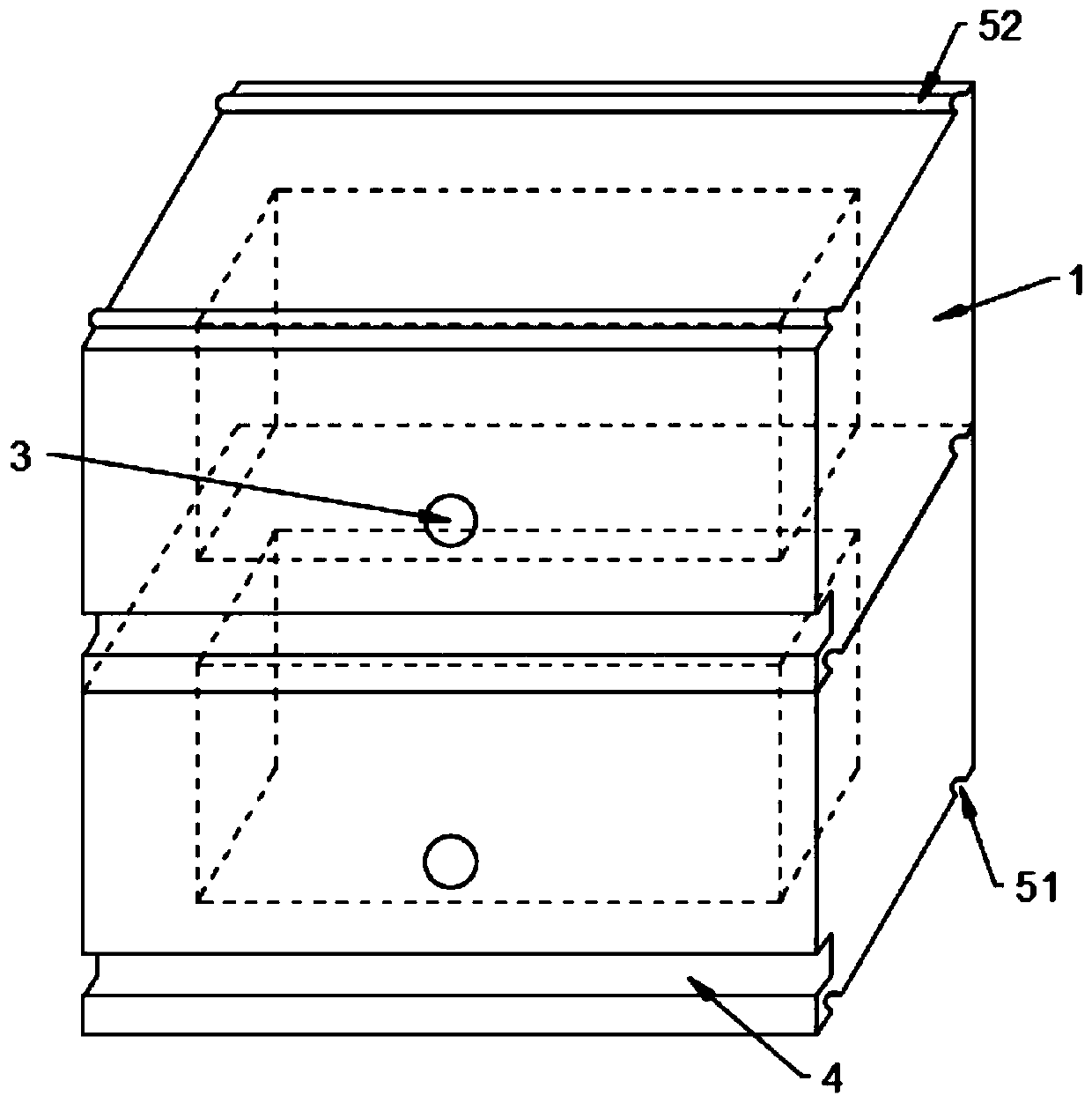
[0038] Such as Figure 1-3 As shown, a simulated ice brick has an ice brick body 1, the ice brick body 1 is a hollow structure, and the bottom of the ice brick body 1 is provided with an opening 2 communicating with the outside world; A spray hole 3 communicating with the hollow structure is provided on the side, and a spray device or a spray pipeline is set in the hollow structure during use, and then the spray port of the spray device or spray pipeline is arranged in the spray hole 3; A bayonet 4 is provided at the bottom of the side of the ice brick body 1 where the spray hole 3 is located.
[0039] Specifically, the bottom side of the ice brick body 1 of the ice brick body 1 is provided with two connecting tenon grooves 51, and the top side is provided with two corresponding raised connecting tenons 52; several ice brick bodies 1 pass through The interlocking of the connecting tenon groove 51 and the connecting tenon 52 are stacked up and down and fixed.
[0040] The ice...
Embodiment 3
[0044] Such as figure 1 , 2 And shown in 4, a kind of artificial ice block has an ice block body 1, and described ice block body 1 is hollow structure, and the bottom of ice block body 1 is provided with the opening 2 that communicates with the outside; One side is provided with the spray hole 3 that is communicated with described hollow structure, and spraying device or spray pipe are set in described hollow structure during use, then the spray mouth of described spray device or spray pipe is arranged on described spray hole 3 Middle; a bayonet 4 is provided at the bottom of the side of the ice block body 1 where the spray hole 3 is located.
[0045] Specifically, the left side of the ice brick body 1 is provided with a connecting tenon groove 51, and the right side is provided with a corresponding raised connecting tenon 52; The interlocking tenon 52 is connected and fixed on the left and right sides; at the same time, a first light belt wiring groove 61 is provided on the...
PUM
 Abstract
Description
Claims
Application Information
 - R&D
- Intellectual Property
- Life Sciences
- Materials
- Tech Scout
- Unparalleled Data Quality
- Higher Quality Content
- 60% Fewer Hallucinations
Browse by: Latest US Patents, China's latest patents, Technical Efficacy Thesaurus, Application Domain, Technology Topic, Popular Technical Reports.
© 2025 PatSnap. All rights reserved.Legal|Privacy policy|Modern Slavery Act Transparency Statement|Sitemap|About US| Contact US: help@patsnap.com