Detachable prefabricated modular shear wall based on profile steel connection, and assembly method thereof
A shear wall and prefabricated formwork technology, applied to walls, buildings, building components, etc., can solve the problems of poor popularization, labor and time-consuming, complicated operation, etc., and achieve the effects of saving construction costs, easier inspection of quality, and accurate positioning
- Summary
- Abstract
- Description
- Claims
- Application Information
AI Technical Summary
Problems solved by technology
Method used
Image

Examples
Embodiment 1
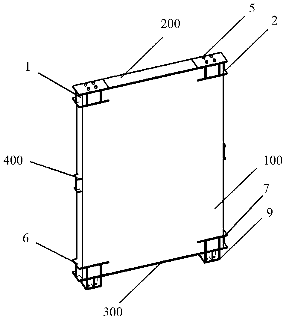
[0032] Depend on figure 1 As shown, the present invention provides a detachable prefabricated modular shear wall (hereinafter referred to as: wall) based on section steel connection. Meet the strong node design requirements. The use of section steel as the connection method of prefabricated components can provide more accurate positioning, faster installation, easier quality inspection, and construction cost savings than traditional wet connections.
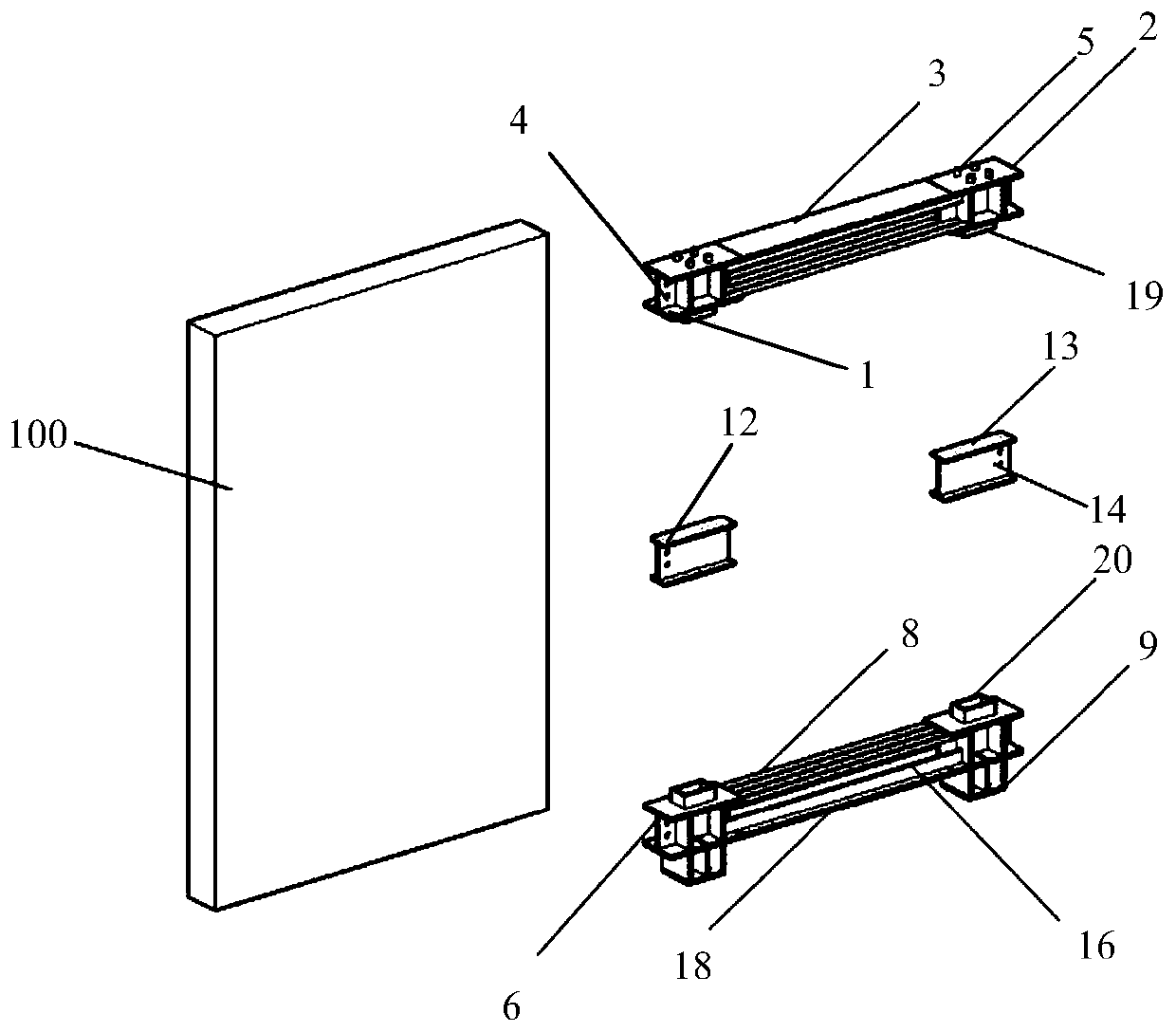
[0033] Such as figure 2 As shown, the present invention includes a reinforced concrete wall 100, an upper steel connector 200, a lower steel connector 300 and an intermediate reinforced connector 400, an upper steel connector 200, a lower steel connector 300 and an intermediate reinforced connector 400 are pre-embedded at the top, bottom and middle of the reinforced concrete wall 100 respectively.
[0034] Among them, such as figure 1 , 2 , 3, the two ends of the upper steel connector 200 are respectively provided with the ...
Embodiment 2
[0041] On the basis of Embodiment 1, the present invention is also provided with a strip-shaped steel plate, which is used to realize the fixing of the vertical reinforcement in the wall. as follows:
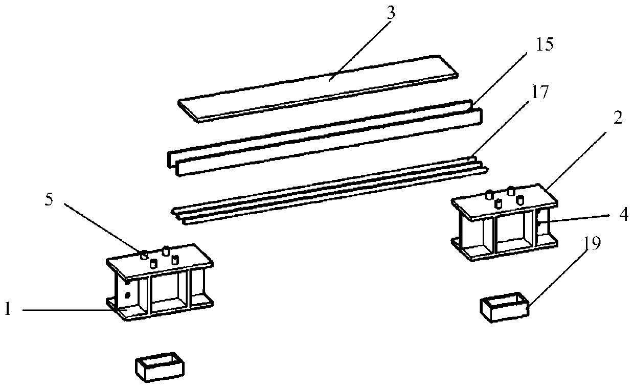
[0042] Such as image 3 As shown, the upper steel connector 200 also includes an upper bar-shaped steel plate 15, and the upper bar-shaped steel plate 15 appears in pairs and is welded and fixed between the first I-shaped steel plate 1, the second I-shaped steel plate 2 and the bottom of the upper steel plate 3 , the bottom of the upper strip steel plate 15 is welded to the end of the vertical reinforcement in the reinforced concrete wall 100 .
[0043] Similarly, such as Figure 4 As shown, the lower steel connector 300 also includes a lower bar-shaped steel plate 16, the lower bar-shaped steel plate 16 appears in pairs and is welded and fixed between the third I-shaped steel plate 6, the fourth I-shaped steel plate 7 and the bottom of the lower steel plate 8 , the top of th...
Embodiment 3
[0046] On the basis of Embodiment 2, the present invention is also provided with a plurality of side-by-side steel bars, and the steel bars replace the steel plate flanges, which can strengthen the connection between the built-in steel connector and the reinforced concrete wall. as follows:
[0047] Such as image 3 As shown, the upper steel connector 200 also includes a plurality of upper steel bars 17, and each upper steel bar 17 is connected with the first I-shaped steel plate 1 and the second I-shaped steel plate 2 after being arranged side by side. bottom.
[0048] Similarly, such as Figure 4 As shown, the lower steel connector 300 also includes a plurality of lower steel bars 18, and each lower steel bar 18 is connected with the third I-shaped steel plate 6 and the fourth I-shaped steel plate 7 after being arranged side by side, and each lower steel bar 18 is located at the bottom of the lower bar-shaped steel plate 16. bottom.
PUM
 Abstract
Description
Claims
Application Information