A two-stage integrated planar movable gear reducer based on guide frame coupling

A technology of movable tooth reducer and guide frame, which is applied in the direction of gear transmission, belt/chain/gear, transmission device, etc., and can solve the problem of small transmission, enlarged mechanism size and small axial dimension of single-stage planar movable tooth reducer and other problems, to achieve the effect of improving application potential, improving self-balancing, and avoiding swinging

Active Publication Date: 2020-12-22
YANSHAN UNIV
View PDF16 Cites 0 Cited by
  • Summary
  • Abstract
  • Description
  • Claims
  • Application Information

AI Technical Summary

Problems solved by technology

[0002] With the continuous development of movable tooth transmission, many new movable tooth reducers have come out one after another. The patent application number is CN201510629776.4, which is a movable tooth cam mechanism output through the swing plate. By changing the tooth profile curve of the closed groove of the swing plate, it can realize The constant speed input is converted into various forms of swing cam output motion. Through multi-stage series connection, although a large reduction ratio transmission can be realized, the size of the mechanism is significantly increased, and it is not suitable for applications in fields limited by space size such as drilling platforms and robot joints. In China, especially with the rapid development of science and technology, there is an urgent need for a new type of transmission device with small size, light weight and large transmission ratio. The planar movable tooth reducer is a representative transmission type in the movable tooth transmission. The raceway on the end face of the gear and the center wheel is processed in the plane, and the manufacturing process is good, but the transmission of the single-stage planar movable tooth reducer is relatively small. If multiple single-stage planar movable tooth reducers are connected in series, although large transmission can be achieved ratio, but the axial dimension is large and the application is limited. Therefore, a two-stage integrated planar movable tooth reducer with the advantages of a planar movable tooth reducer and a small axial dimension can be developed while achieving a large transmission ratio. The reducer can be applied to the development needs of more new technologies and new equipment

Method used


Image

  • A two-stage integrated planar movable gear reducer based on guide frame coupling
  • A two-stage integrated planar movable gear reducer based on guide frame coupling
  • A two-stage integrated planar movable gear reducer based on guide frame coupling

Examples


Embodiment Construction

[0023] In order to make the purpose, technical solutions and advantages of the embodiments of the present invention clearer, the technical solutions in the embodiments of the present invention will be clearly and completely described below in conjunction with the drawings in the embodiments of the present invention. Obviously, the described embodiments It is a part of embodiments of the present invention, but not all embodiments.

[0024] In describing the present invention, it is to be understood that the terms "radial", "axial", "upper", "lower", "top", "bottom", "inner", "outer" etc. indicate orientation Or the positional relationship is based on the orientation or positional relationship shown in the drawings, which is only for the convenience of describing the present invention and simplifying the description, and does not indicate or imply that the referred device or element must have a specific orientation, be constructed and operated in a specific orientation , and the...


PUM


Abstract

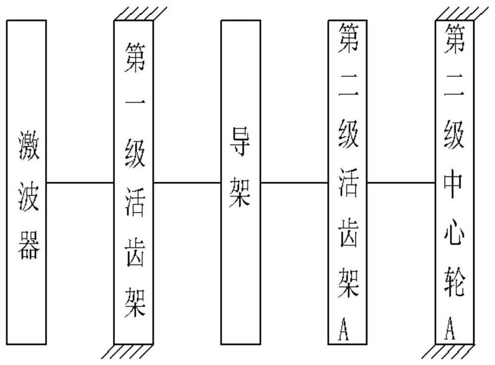
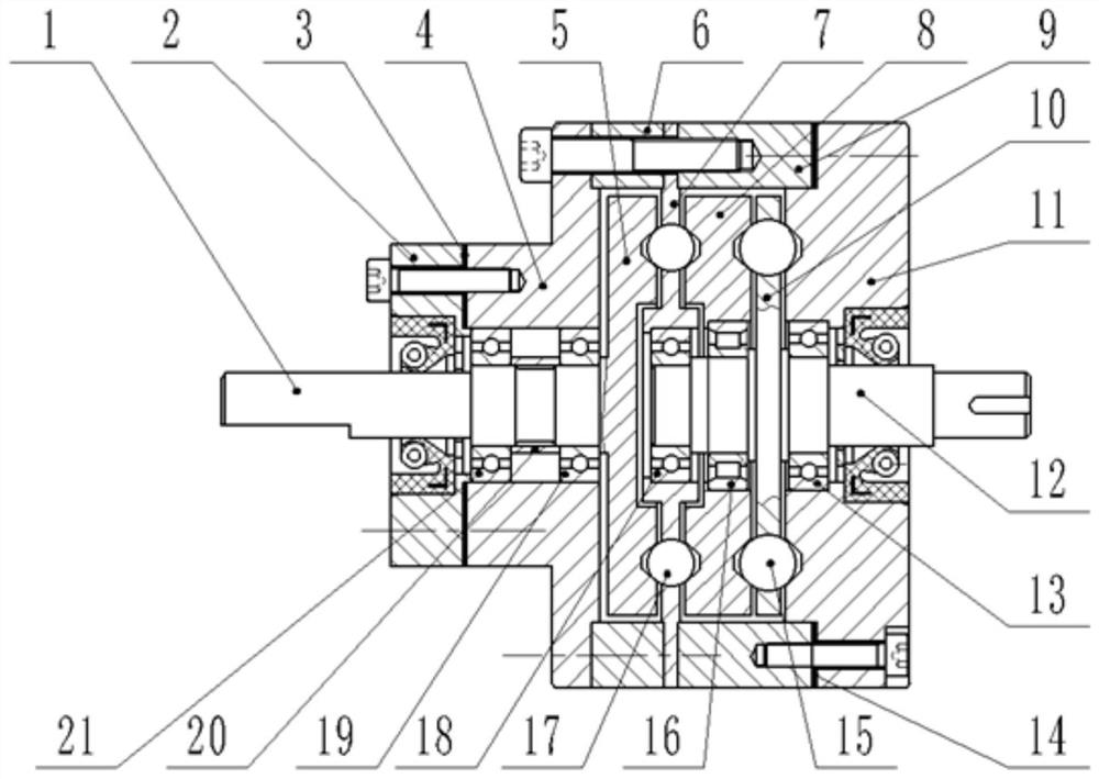
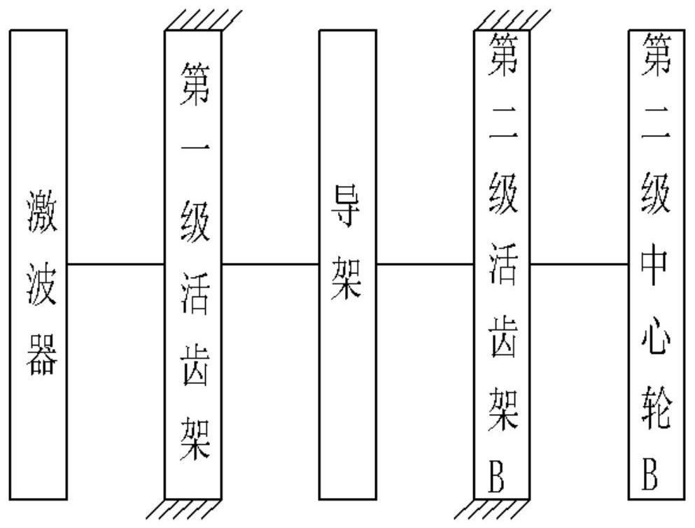
The invention discloses a two-stage integrated plane oscillating tooth speed reducer based on guiding frame coupling. A guiding frame is designed through integration of first-stage power output and second-stage power input, in first-stage transmission, a wave generator and an input shaft are designed into a wave exciter of an integrated concentric structure, a first-stage oscillating tooth carrieris fixed, the wave exciter is arranged at the input end of the first-stage oscillating tooth carrier, and the guiding frame is arranged at the output end of the first-stage oscillating tooth carrier,in second-stage transmission, a shaft-type output structure and a disc-type output structure can be designed according to the actual engineering requirements, as for the shaft-type output structure,a second-stage center wheel A is fixed, a second-stage oscillating tooth carrier A drives an output shaft to output power; and as for the disc-type output structure, a second-stage oscillating tooth carrier B is fixed, and a second-stage center wheel B outputs power. The two-stage integrated plane oscillating tooth speed reducer is stable in transmission, flexible and reliable, and has the advantages of good self-balancing performance, compact structure and the like.

Description

technical field [0001] The invention relates to a movable tooth transmission device, in particular to a dual-stage integrated planar movable tooth reducer based on guide frame coupling. Background technique [0002] With the continuous development of movable tooth transmission, many new movable tooth reducers have come out one after another. The patent application number is CN201510629776.4, which is a movable tooth cam mechanism output through the swing plate. By changing the tooth profile curve of the closed groove of the swing plate, it can realize The constant speed input is converted into various forms of swing cam output motion. Through multi-stage series connection, although a large reduction ratio transmission can be realized, the size of the mechanism is significantly increased, and it is not suitable for applications in fields such as drilling platforms and robot joints that are limited by space size. In China, especially with the rapid development of science and t...

Claims


Application Information

Patent Timeline
Patent Type & Authority Patents(China)
IPC IPC(8): F16H1/32F16H49/00F16H57/023F16H57/028
Inventor 许立忠马鹏飞
Owner YANSHAN UNIV
Why Eureka
Try Eureka