Online monitoring system and method of micro-leakage of low-pressure gas pipeline

A gas pipeline and monitoring system technology, applied in pipeline systems, measuring devices, gas/liquid distribution and storage, etc., can solve the problems of difficulty in small leaks, detection and judgment of leak locations, etc.

Pending Publication Date: 2019-05-03
HEFEI INST FOR PUBLIC SAFETY RES TSINGHUA UNIV +1
View PDF0 Cites 2 Cited by
  • Summary
  • Abstract
  • Description
  • Claims
  • Application Information

AI Technical Summary

Problems solved by technology

[0003] The pressure monitoring method is suitable for monitoring large leaks in high-pressure pipelines. It is difficult to monitor small leaks in urban low-pressure pipelines by pressure monitoring methods, and the positioning range is t

Method used


Image

  • Online monitoring system and method of micro-leakage of low-pressure gas pipeline
  • Online monitoring system and method of micro-leakage of low-pressure gas pipeline
  • Online monitoring system and method of micro-leakage of low-pressure gas pipeline

Examples


Embodiment 1

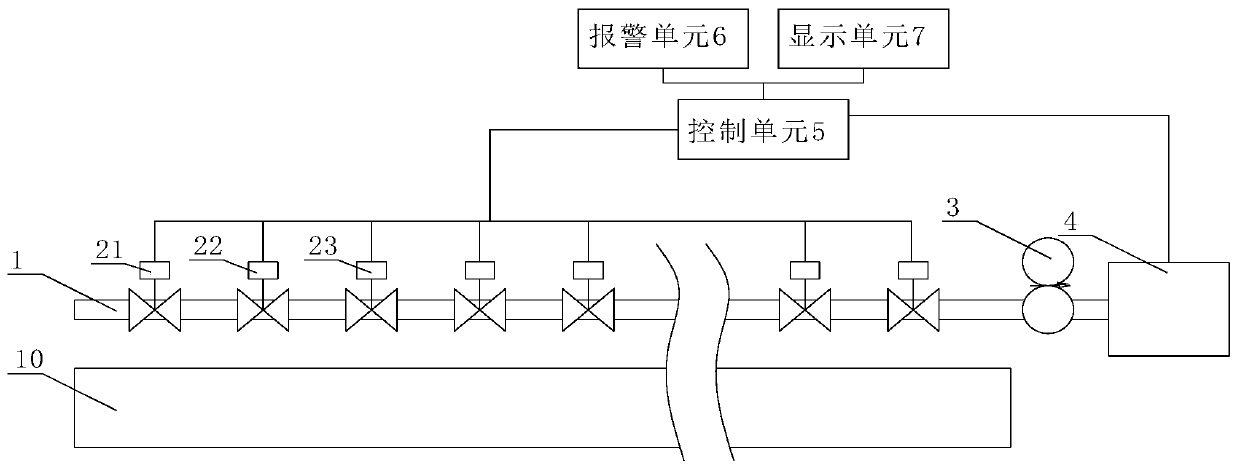
[0031] Such as figure 1 As shown, an on-line monitoring system for micro-leakage of low-pressure gas pipelines includes an air suction pipeline 1 for absorbing gas in the gas pipeline 10 and a control unit 5. An air suction pump 3 is arranged at the end of the air suction pipeline 1. 1. A concentration detector 4 is arranged on the end surface close to the suction pump 3; multiple groups of suction holes are sequentially arranged in the length direction of the suction pipeline 1, and electric valves are arranged between each adjacent two groups of suction holes. Each electric valve is used to throttle the suction pipe 1 at the front end of the electric valve, and the electric valve is connected with the control unit 5 . The electric valve can be a solenoid valve.

[0032] In this embodiment, the air suction pipeline 1 is a thin tube arranged above the gas pipeline 10 . There is one suction hole in each group, and it is arranged opposite to the gas pipeline 10 . Since the de...

Embodiment 2

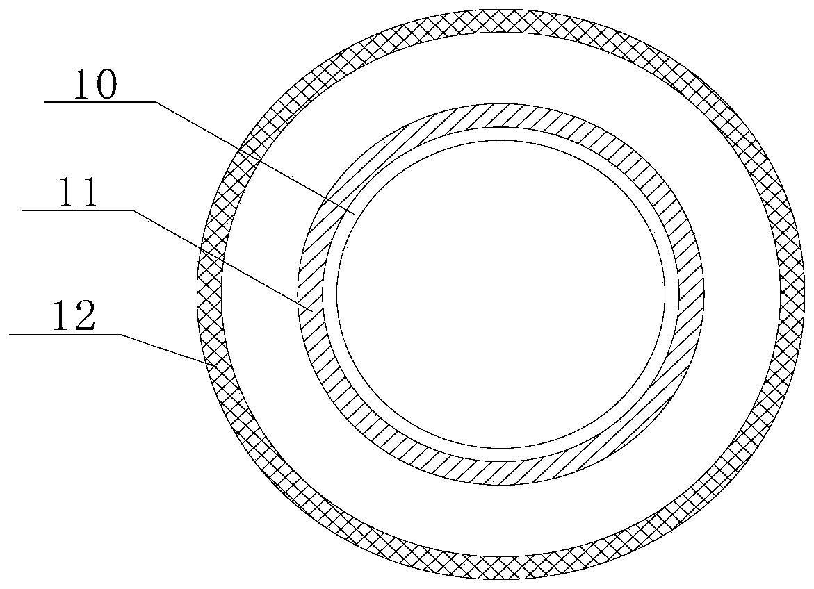
[0036] Such as figure 2 As shown, the difference from Embodiment 1 is that the suction pipe 1 is an annular pipe wrapped on the gas pipe 10, and the annular pipe includes an inner ring 11 that is close to the outer wall of the outer wall of the gas pipe 10, and an inner ring 11 concentric outer ring 12. There are several suction holes in each group, which are arranged in a ring on the inner ring 11 . When the leakage point is located at the unopened air suction hole of the inner ring 11, the suction pipe 1 can also play a role in preventing air leakage. When the leakage point is relatively large, the system can also monitor it.

Embodiment 3

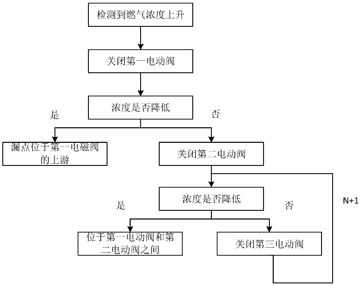
[0038] Such as image 3 As shown, the method of using any one of the low-pressure gas pipeline micro-leakage online monitoring systems in the above two embodiments includes the following steps:

[0039] S1, all electric valves are open, the suction pump 3 works, and the gas is input into the concentration detector 4; the safe concentration value is set in the control unit 5, and a comparison module is arranged in the control unit 5, and the concentration detector 4 will The data is sent to the control unit 5. When the value input by the concentration detector 4 to the control unit 5 is greater than the safe concentration value, the control unit 5 controls the alarm unit 6 to work and automatically enters step S2.

[0040] S2, when the numerical value in the concentration detector 4 rises, the control unit 5 closes the first electric valve 21 farthest away from the concentration detector 4, after setting time, whether the concentration detected by the concentration detector 4 d...


PUM


Abstract

The invention discloses an online monitoring system and method of micro-leakage of a low-pressure gas pipeline. A device comprises a gas sucking pipeline for sucking gas in the gas pipeline, and a control unit; a gas sucking pump is arranged at the end of the gas sucking pipeline, and a concentration detector is arranged on the end face, close to the gas sucking pump, of the gas sucking pipeline;and a plurality of gas sucking holes are sequentially formed in the length direction of the gas sucking pipeline, an electric valve is arranged between every two adjacent sets of the gas sucking holesand used for throttling the gas sucking pipeline at the front end of the electric valve, and the electric valves are connected with the control unit. The online monitoring system and method have theadvantages that after a certain position of the gas pipeline leaks, under the effect of the gas sucking pump, the negative pressure exists in the pipeline with the holes, thus gas enters the gas sucking pipeline from the nearest gas sucking hole, and is pumped to an outlet to enter the concentration detector, and then the electric valves of all sections are controlled through the control unit, sothat the leakage point is determined. The system and the method can be used for leakage detection of the low-pressure pipeline.

Description

technical field [0001] The invention relates to the technical field of gas pipeline monitoring, in particular to an online monitoring system and method for micro-leakage of low-pressure gas pipelines. Background technique [0002] The gas pipeline network spreads all over the city. Explosion accidents caused by leakage of gas pipeline network pose a great threat to the safety of the city. For the leakage monitoring of urban gas pipeline network, it mainly includes the pressure monitoring method, the combustible gas concentration monitoring method in the adjacent space of the gas pipeline, etc. The pressure monitoring method is to install a pressure gauge on the gas pipeline to monitor the operation status of the gas pipeline. When the gas pipeline leaks, the pressure of the gas pipeline will change. The combustible gas concentration monitoring method in the adjacent space of the gas pipeline is to place the monitoring equipment in the underground space adjacent to the gas ...

Claims


Application Information

Patent Timeline
IPC IPC(8): F17D5/00F17D5/02G01N33/00
Inventor 许令顺袁宏永苏国锋陈涛付明汪曙光王琨李祥东孙光辉
Owner HEFEI INST FOR PUBLIC SAFETY RES TSINGHUA UNIV
Why Eureka
Try Eureka