
Novel wet cooling tower with internal and external coordinated optimization of intake air

A wet cooling and cooling system technology, applied in water shower coolers, heat exchanger types, direct contact heat exchangers, etc. and other problems, to achieve the effect of strengthening heat and mass transfer performance, improving cooling efficiency, and reducing adverse effects

Active Publication Date: 2019-05-03
SHANDONG UNIV
View PDF6 Cites 1 Cited by
  • Summary
  • Abstract
  • Description
  • Claims
  • Application Information

AI Technical Summary

Problems solved by technology

The high water density in the rain area increases the ventilation resistance of the cooling tower, and it is difficult for the cold air from the outside to enter the center of the tower, resulting in a decrease in the uniformity of the flow field in the tower, reducing the ventilation volume of the cooling tower, and reducing the heat transfer in the rain area. Quality and performance
The deterioration of the ventilation performance in the rain zone directly affects the ventilation characteristics of the packing area, and then affects the heat and mass transfer performance of the packing area and the water distribution area, thus deteriorating the overall thermal performance of the whole tower
[0004] The inventors of the present invention have found that crosswinds generally exist during the operation of the cooling tower, which seriously affects the uniformity of the cooling tower's circumferential air intake, increases the air intake resistance, and reduces the ventilation volume of the cooling tower

Method used


Image

  • Novel wet cooling tower with internal and external coordinated optimization of intake air
  • Novel wet cooling tower with internal and external coordinated optimization of intake air
  • Novel wet cooling tower with internal and external coordinated optimization of intake air

Examples


Embodiment Construction

[0018] It should be noted that the following detailed description is exemplary and intended to provide further explanation of the present disclosure. Unless defined otherwise, all technical and scientific terms used herein have the same meaning as commonly understood by one of ordinary skill in the art to which this disclosure belongs.

[0019] It should be noted that the terminology used herein is only for describing specific embodiments, and is not intended to limit the exemplary embodiments according to the present disclosure. As used herein, unless the context clearly dictates otherwise, the singular is intended to include the plural, and it should also be understood that when the terms "comprising" and / or "comprising" are used in this specification, they mean There are features, steps, operations, means, components and / or combinations thereof.

[0020] In view of the fact that crosswinds generally affect the ventilation of cooling towers during the operation of cooling t...


PUM


Abstract

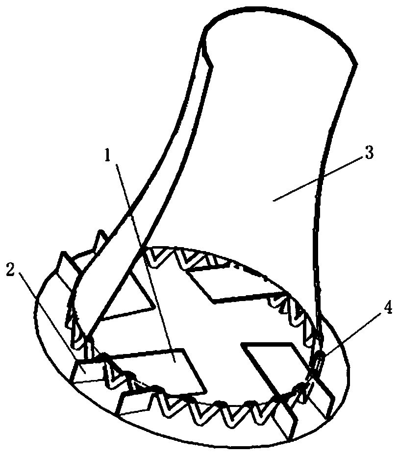
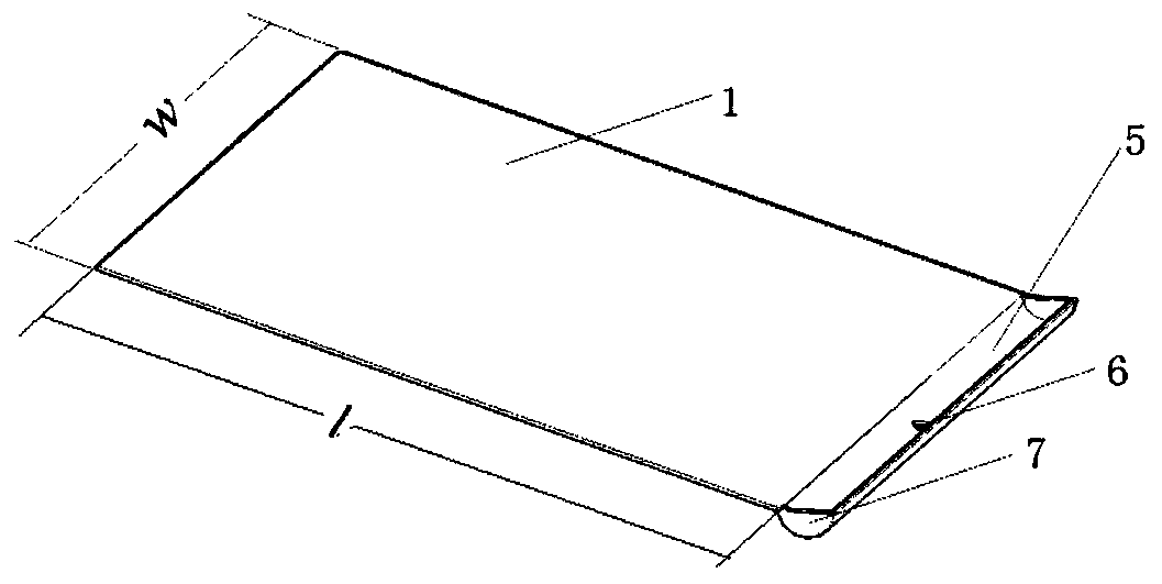
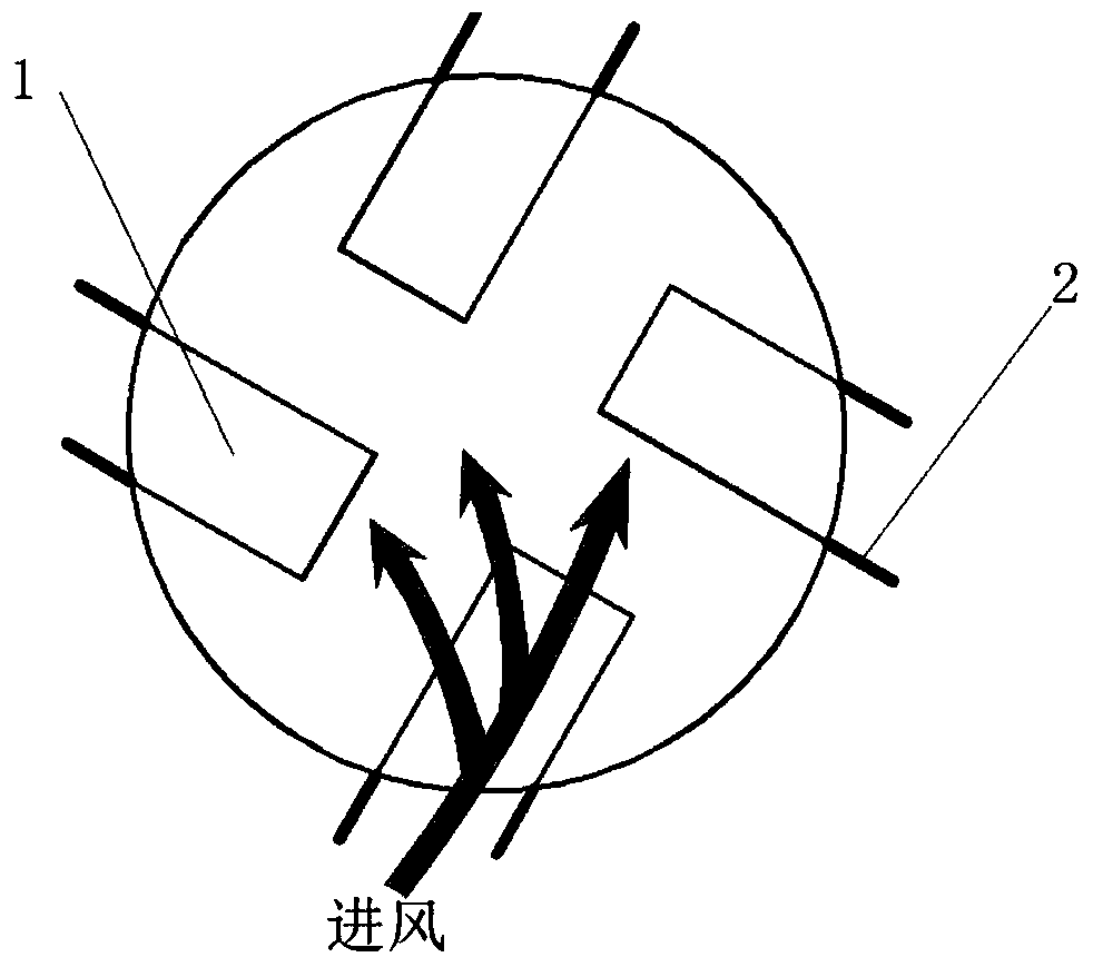
The invention discloses a rain-area dry and wet mixed cooling system with internal and external coordination of a natural draft wet cooling tower. The rain-area dry and wet mixed cooling system comprises the natural draft wet cooling tower, and a plurality of flow distribution plates are arranged in the rain area of the natural draft wet cooling tower. Each flow distribution plate is of a plate-shape structure, one end of the flow distribution plate is connected onto a tower wall of the natural draft wet cooling tower, and the other end of the flow distribution plate points to the adjacent flow distribution plate. The two sides of each flow distribution plate are arranged obliquely, and one side, close to the tower wall of the cooling tower, of the flow distribution plate is lower than theother side of the flow distribution plate. All the flow distribution plates show rotational symmetry about the center of the radial section of the super large wet cooling tower. The part of the rainarea covered by one flow distribution plate forms a dry area, and an air inlet in the bottom of the natural draft wet cooling tower is divided into a plurality of dry area inlets and a plurality of rain area inlets by a plurality of dry areas. Air deflectors are vertically arranged on the two sides of the ground of each dry area inlet, and the air deflectors are arranged on the outer side of the tower wall.

Description

technical field [0001] The invention relates to the field of energy and power engineering, in particular to a novel natural ventilation wet cooling tower which coordinates and optimizes the air intake inside and outside. Background technique [0002] The statements herein merely provide background information related to the present invention and may not necessarily constitute prior art. [0003] The internal area of ​​a conventional wet cooling tower is generally divided into a water distribution area, a fill area, and a rain area. The high water density in the rain area increases the ventilation resistance of the cooling tower, and it is difficult for the cold air from the outside to enter the center of the tower, resulting in a decrease in the uniformity of the flow field in the tower, reducing the ventilation volume of the cooling tower, and reducing the heat transfer in the rain area. qualitative performance. The deterioration of the ventilation performance of the rain...

Claims


Application Information

Patent Timeline
IPC IPC(8): F28C1/00F28F25/00F28F25/02F28F25/12
Inventor 史月涛张政清高明何锁盈
Owner SHANDONG UNIV
Learn More