

Explosive charging equipment of charging plate
A technology for loading equipment and charging plates, which is applied in the direction of offensive equipment, ammunition, weapon accessories, etc., can solve problems such as low automation, restricting industry development, and potential safety hazards, so as to improve accuracy and efficiency, improve safety performance, and improve safety. Guaranteed effect
- Summary
- Abstract
- Description
- Claims
- Application Information
AI Technical Summary
Problems solved by technology
Method used
Image

Examples
Embodiment 1
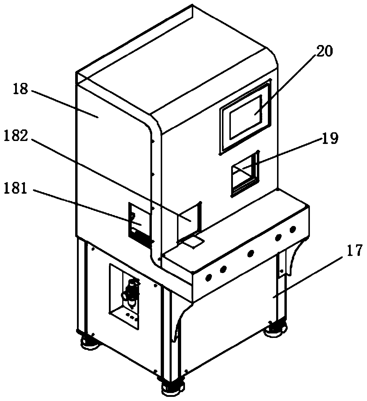
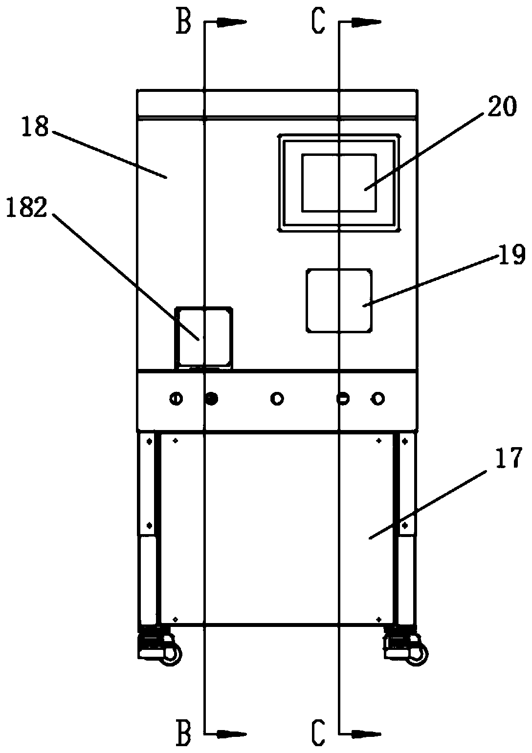
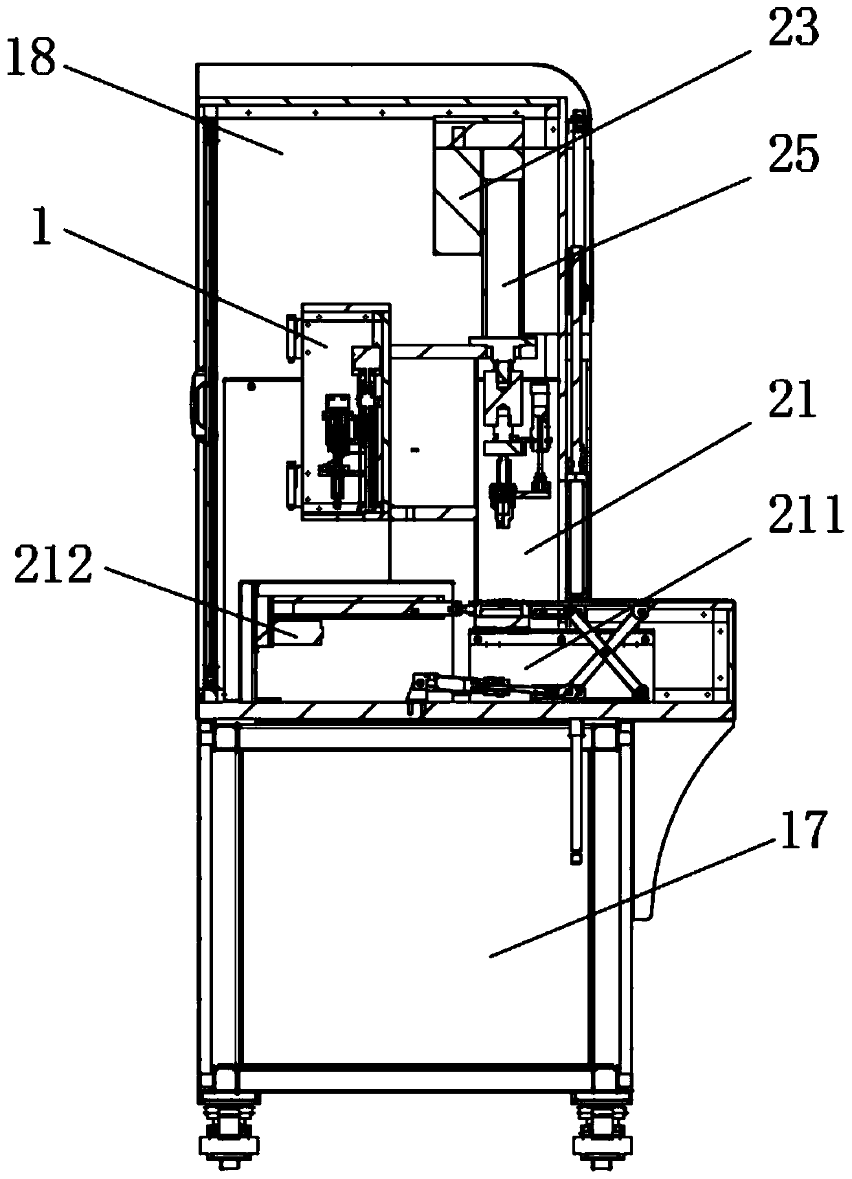
[0035] Such as figure 1 , figure 2 , image 3 As shown, in this embodiment, a charge plate explosive filling equipment includes a frame 17, an explosion-proof cover 18 arranged on the frame 17, an explosive that is arranged on the inner surface of the explosion-proof cover 18 and is used to quantitatively output the explosive The extruding device, the explosive pressing device arranged in the explosion-proof cover 18, and the charging plate 210 arranged under the explosive pressing device; the discharge hose 10 is connected between the explosive extruding device and the explosive pressing device.
[0036] In this solution, the explosives extruding device is used to uniformly output the explosives to be distributed, and then the explosives are loaded into the charge plate 210 by the explosives pressing device, so as to realize the work of explosives loading. By using mechanical equipment to complete the loading work, it is possible to avoid direct contact of workers with exp...
Embodiment 2
[0038] Such as Figure 4 , Figure 5 As shown, on the basis of the above embodiments, in this embodiment, the explosive extruding device includes a feeding cabinet 1 hinged with a feeding protection door 15, a cup-shaped material provided in the feeding cabinet 1 and having a silo 81. The cup 8, the extruding plunger 6 that is slidingly and sealingly connected with the silo 81, the stirring rod 4 that is arranged in the extruding plunger 6 and can rotate and slide relatively with the extruding plunger 6; the stirring rod 4 One end is connected with a stirring rod driving structure for driving the stirring rod 4 to rotate, and the other end of the stirring rod 4 extends into the feed bin 81; the charging cabinet 1 is provided with a device for driving the extrusion plunger 6 to slide relative to the feed bin 81 Plunger driving structure; the material cup 8 communicates with the discharge hose 10 .
[0039] When in use, put explosives into the silo 81 of the material cup 8, then...
Embodiment 3
[0046] On the basis of the above embodiments, in this embodiment, the agitating rod drive structure includes a cylinder fixing bracket 3 connected to the charging cabinet 1 and a cylinder fixed bracket 3 installed on the cylinder fixing bracket 3 and connected to the agitating rod 4 in transmission. Swing cylinder 2. Setting the cylinder fixing bracket 3 can provide support for the installation of the swing cylinder 2, and can utilize the space position in the middle of the charging cabinet 1, so that the structure can be reasonably arranged and the space utilization rate can be improved. The stirring rod 4 is connected to the swing cylinder 2, and the swing cylinder 2 can be used to drive the stirring rod 4 to rotate back and forth at a slow speed, thereby realizing the function of stirring the explosive and avoiding the rapid friction between the stirring rod 4 and the explosive to increase the risk of explosive explosion . And the vibration generated by the oscillating cyl...
PUM
 Abstract
Description
Claims
Application Information