New ultra-high precision electromagnetic electronic balance

An electronic balance and electromagnetic technology, applied in the field of new ultra-high-precision electromagnetic electronic balances, can solve the problems of difficulty in guaranteeing electromagnetic balance sensor coils and magnetic steel, hindering the application of electromagnetic balance sensors, and uneven coil wall thickness, etc. Stability and correctness, easy installation and debugging, and the effect of reducing production costs

Inactive Publication Date: 2019-05-03
CHANGZHOU KEYUAN ELECTRONICS INSTR
View PDF0 Cites 0 Cited by
  • Summary
  • Abstract
  • Description
  • Claims
  • Application Information

AI Technical Summary

Problems solved by technology

In fact, the gap between the magnetic steel is 2mm, the error is 0.02mm, the inner and outer wall thickness of the coil is 1.5mm, the error is 0.02mm, and there will be deviations between the magnetic pole and the AlNiCo and the magnetic steel sleeve, and the coil wall thickness will also be uneven; in fact, the coil is installed The ideal gap in the magnetic steel is only 0.1~0.2mm
[0005] Due to the above reasons, most domestic manufacturers of electromagnetic balance sensors and electronic balances are difficult to ensure that the gap is 100% correct when producing electromagnetic balance sensor coils and magnetic steel installations.
Seriously hinders the application of electromagnetic balance sensors in higher precision electronic balances

Method used


Image

  • New ultra-high precision electromagnetic electronic balance
  • New ultra-high precision electromagnetic electronic balance
  • New ultra-high precision electromagnetic electronic balance

Examples


Embodiment 1

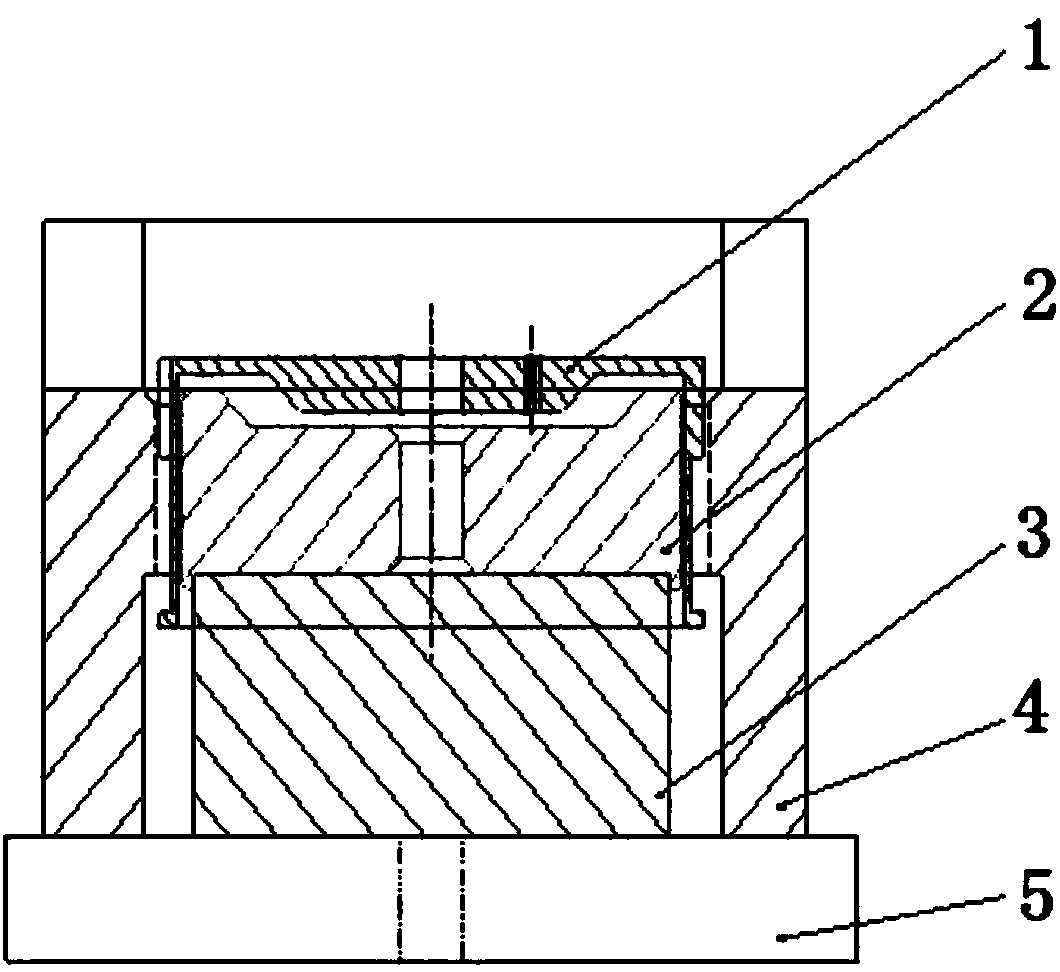
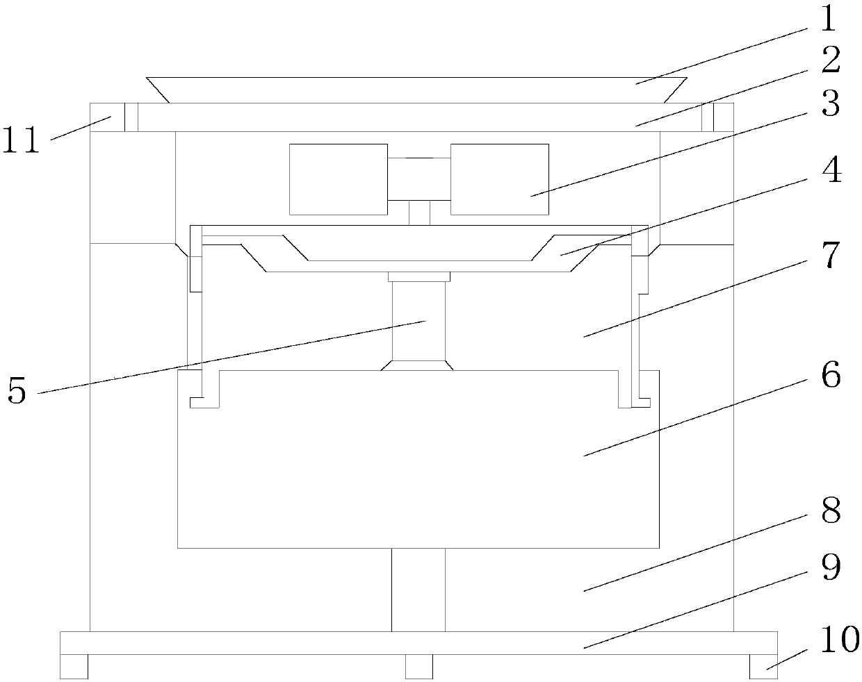
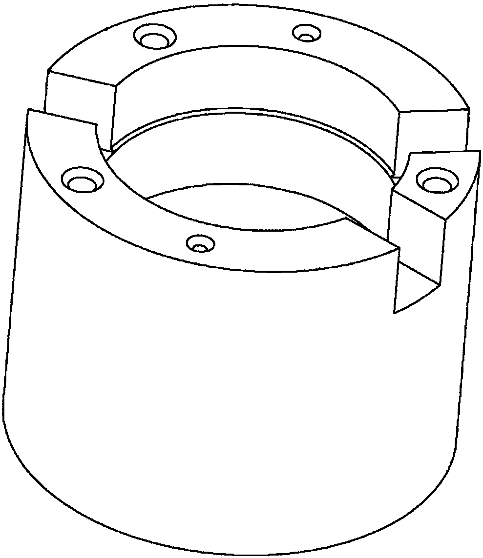
[0021] See figure 2 and image 3 , the present invention has a weighing pan 1 placed on the upper end of the windshield casing; the weighing pan 1 is fixed on the bracket 2; the sensor assembly placed in the windshield casing is installed below the bracket 2; the sensor assembly includes a bracket, a magnetic steel 6. The magnetic pole 7 and the coil 4; the bubble balancer 3 is installed under the bracket 2; the bubble balancer 3 is connected to the magnetic steel 6 installed in the windshield casing through the connecting rod 5; the connecting rod 5 is sleeved with the bottom and The magnetic pole 7 which is in contact with the upper surface of the magnetic steel 6 and the coil 4 whose bottom is in contact with the upper surface of the magnetic pole 7; the outer side of the magnetic steel 6 is covered with a seat cover 8 which is composed of a magnetic steel cover and a magnetic steel base; The accommodating cavity of the magnetic steel has a bottom plate 9 under the seat c...


PUM


Abstract

The invention relates to a new ultra-high precision electromagnetic electronic balance. The electronic balance comprises a scale pan arranged at an upper end of a wind cap casing, wherein the scale pan is fixed on a bracket, a lower portion of the bracket is equipped with a sensor assembly arranged in the wind cap casing, the sensor assembly includes a support, a magnetic steel, magnetic poles anda coil, a lower portion of the bracket is equipped with a bubble balancing instrument, the bubble balancing instrument is connected with the magnetic steel mounted in the wind cap casing through a connection rod, the connection rod is sleeved with the magnetic poles of which bottom portions are in contact with an upper surface of the magnetic steel and the coil of which a bottom portion is in contact with upper surfaces of the magnetic poles, an outer side of the magnetic steel is sleeved with a seat sleeve composed of a magnetic steel sleeve and a magnetic steel base, and a lower portion ofthe seat sleeve has a bottom plate. The electronic balance is advantaged in that performance of an electromagnetic balancing sensor is improved, production cost is reduced, and stability and accuracyof the electromagnetic balancing sensor are improved.

Description

technical field [0001] The invention relates to the field of electronic instruments, in particular to a novel ultra-high-precision electromagnetic electronic balance. Background technique [0002] People call a balance that uses electromagnetic force to balance the gravity of an object to be called an electronic balance. It is characterized by accurate and reliable weighing and fast and clear display, and has automatic detection system, simple automatic calibration device and overload protection device. Electronic balance is used to weigh the mass of objects. Electronic balances generally use electronic instruments of strain gauge sensors, capacitive sensors and electromagnetic balance sensors. Strain sensor has simple structure and low cost, but its accuracy is limited. Before 2009, high precision cannot be achieved; capacitive sensors have fast weighing speed and high cost performance, but they cannot achieve high precision; electronic balances using electromagnetic bal...

Claims


Application Information

Patent Timeline
Patent Type & Authority Applications(China)
IPC IPC(8): G01G7/02
Inventor 陈琴逸
Owner CHANGZHOU KEYUAN ELECTRONICS INSTR
Why Eureka
Try Eureka