
Illumination control method and device for controlling illumination equipment

A lighting control and lighting control technology, applied in optical testing flaws/defects, semiconductor/solid-state device testing/measurement, electrical components, etc., can solve problems such as yield loss and semiconductor chip quality problems, reduce energy consumption, improve Reflectivity, the effect of clearly identifying abnormal object images

Active Publication Date: 2020-04-07
INTEL PROD CHENGDU CO LTD +1
View PDF8 Cites 0 Cited by
  • Summary
  • Abstract
  • Description
  • Claims
  • Application Information

AI Technical Summary

Problems solved by technology

Therefore, when the above-mentioned abnormalities exist in the chip socket, it may cause quality problems in a large number of semiconductor chips, resulting in yield loss
[0003] In the prior art, quality problems caused by abnormal equipment components cannot be detected by inspection tools until the products processed by the abnormal equipment components reach a specific inspection process
However, by the time the inspection tools detected these quality problems, a large number of products had been processed by abnormal equipment parts
Therefore, because the existing technology cannot detect the abnormality of the equipment components in time, the yield has been lost when the equipment components are found to be abnormal.

Method used


Image

  • Illumination control method and device for controlling illumination equipment
  • Illumination control method and device for controlling illumination equipment
  • Illumination control method and device for controlling illumination equipment

Examples


Embodiment Construction

[0055] The subject matter described herein will be discussed below with reference to example implementations. It should be understood that the discussion of these implementations is only to enable those skilled in the art to better understand and realize the subject matter described herein, and is not intended to limit the protection scope, applicability or examples set forth in the claims. Changes may be made in the function and arrangement of elements discussed without departing from the scope of the disclosure. Various examples may omit, substitute, or add various procedures or components as needed. Additionally, features described with respect to some examples may also be combined in other examples.

[0056] As used herein, the term "comprising" and its variants represent open terms meaning "including but not limited to". The term "based on" means "based at least in part on". The terms "one embodiment" and "an embodiment" mean "at least one embodiment." The term "anoth...


PUM

PropertyMeasurementUnit
wavelengthaaaaaaaaaa

Abstract

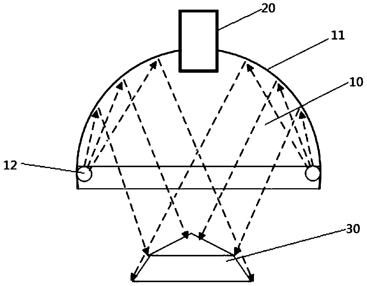
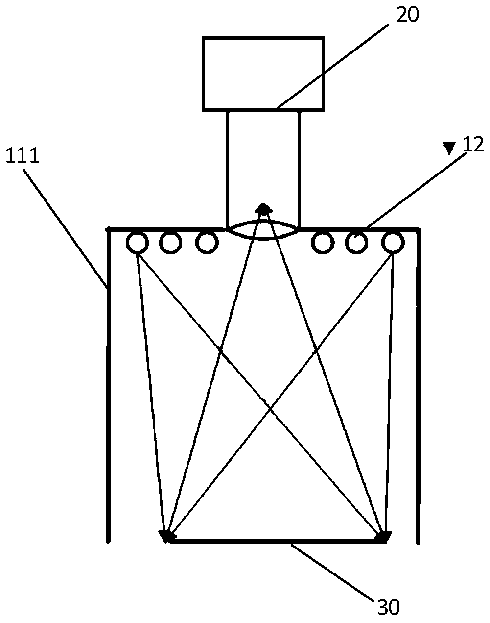
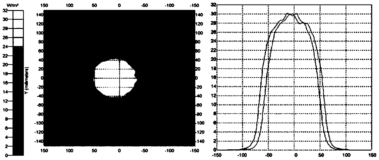
The invention relates to an illumination control method and device for controlling illumination equipment. The illumination equipment includes a curved surface mask with a concave surface and multiplemonochrome visible light sources arranged on the concave surface. Positions of the multiple monochromatic visible light sources and the shape of the curved surface enable the monochromatic visible light emitted by the multiple monochromatic visible light sources to form the illumination light having illuminance deviation of not greater than 10% within a predetermined illumination range to illuminate a to-be-inspected object. The illumination control method includes steps that the illuminance of the monochromatic visible light in the environment in which the to-be-inspected object is located is obtained; when the acquired illuminance of the monochromatic visible light does not reach the predetermined monochromatic visible light illumination threshold, the luminance of the monochromatic visible light sources is controlled for making the illuminance of the monochromatic visible light in the environment in which the to-be-inspected object is placed reaches the monochromatic visible lightilluminance threshold. The method is advantaged in that clear object images can be obtained, and whether the to-be-inspected object is abnormal is determined based on the object images.

Description

technical field [0001] The present disclosure relates to the technical field of object inspection, and in particular, to a lighting control method and device for controlling lighting equipment. Background technique [0002] In the semiconductor manufacturing process, abnormal factors such as damage, foreign matter, and deformation on equipment components will have an impact on the quality of semiconductor products being processed. For example, when testing a semiconductor chip, a chip socket is used, and the chip socket is used to insert the chip to test it. When the pins (Pin) of the chip socket are damaged, foreign objects, deformed, burned and other abnormalities, it may cause quality problems such as indentations on the substrate, leads, solder balls, etc. of the chip. A large number of semiconductor chips can be plugged into the same chip socket. Therefore, when the above-mentioned abnormality exists in the chip socket, quality problems may occur in a large number of ...

Claims


Application Information

Patent Timeline
Patent Type & Authority Patents(China)
IPC IPC(8): G01N21/88H01L21/66H05B47/10
Inventor 周伟程泽
Owner INTEL PROD CHENGDU CO LTD
Learn More