
A pulse processing generation method and device

A technology of pulse processing and generating device, applied in the direction of pulse processing, pulse technology, electrical components, etc., can solve problems such as amplification, and achieve the effect of high-precision control effect

Active Publication Date: 2019-05-03
MASTERWORK GROUP CO LTD
View PDF4 Cites 1 Cited by
  • Summary
  • Abstract
  • Description
  • Claims
  • Application Information

AI Technical Summary

Problems solved by technology

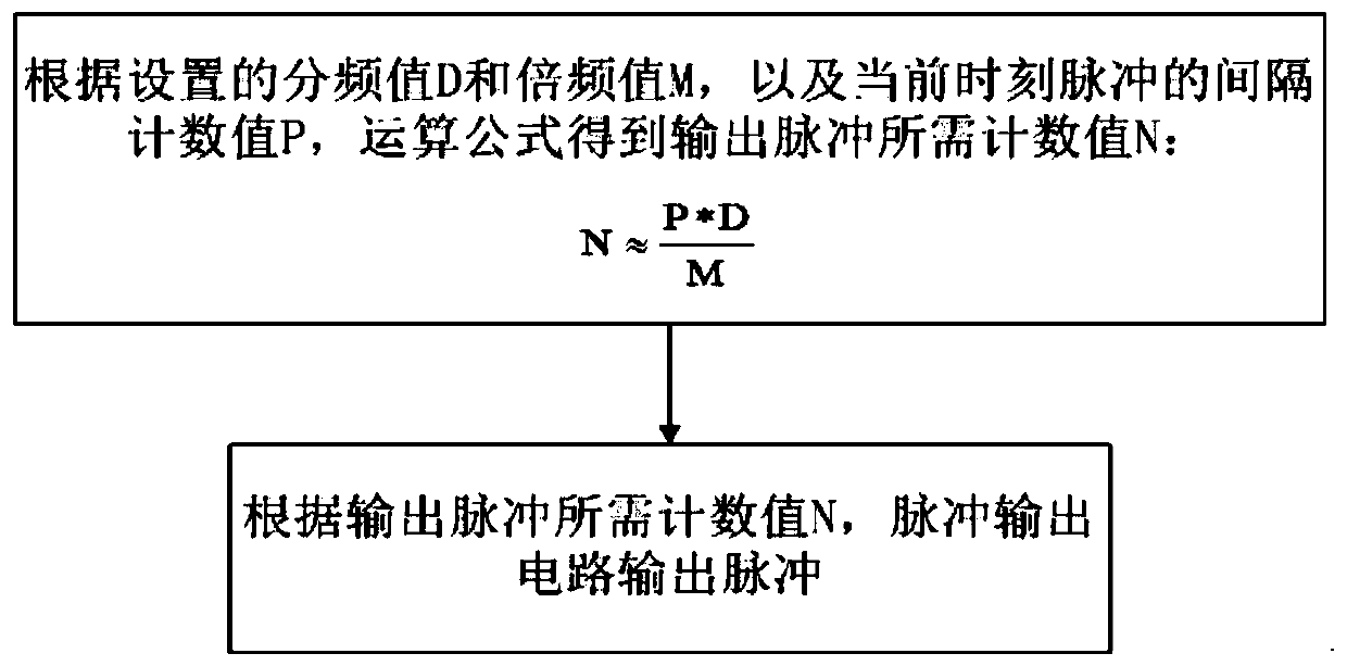
[0005] But it is not difficult to see that the only formula of this scheme, formula The final value of N is the integer part of the result on the right. In the case of low-frequency pulse input, the error caused by the deviation of a few tenths will be amplified due to the reduction of the base (deviation / N ); such as: in the printing production operation, the transmission device mostly relies on the encoder signal as an important basis for actually triggering printing. The pulse signal period P) is 1000, the frequency division number D is 7, and the frequency multiplication number M is 13 (the output pulse period should be 0.54 times the input pulse period), then after calculation, N=538.46..., the deviation of which is only 0.46 It accounts for 0.085% of the final output result; and if the production machine just speeds up or runs at a low speed, the situation will be different. At this time, P is 20, the frequency division number D is 7, and the frequency multiplication number M is 13. After calculation, N =10.76..., at this time, the deviation of 0.76 accounts for 7.6% of the final output result, which confirms the previous statement that the error is amplified; at the same time, this method also restricts the selection of frequency division and multiplication

Method used


Image

  • A pulse processing generation method and device
  • A pulse processing generation method and device
  • A pulse processing generation method and device

Examples


Embodiment Construction

[0024] The present invention will be described in further detail below in conjunction with the accompanying drawings and specific embodiments. It should be understood that the specific embodiments described here are only used to explain the present invention, not to limit the present invention.

[0025] It should be noted that the "connection" mentioned in this application and the words used to express "connection", such as "connected", "connected", etc., include not only a direct connection between a certain component and another component, but also a certain One part is connected to another part through other parts.

[0026] It should be noted that the terminology used here is only for describing specific implementations, and is not intended to limit the exemplary implementations according to the present application. As used herein, unless the context clearly indicates otherwise, the singular form is also intended to include the plural form. In addition, it should also be u...


PUM


Abstract

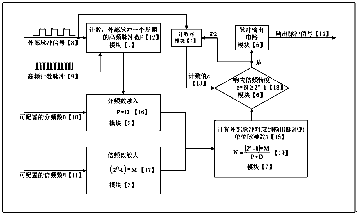
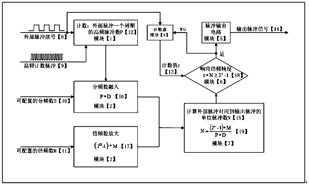
The invention discloses a pulse processing generation method and device. The influence of original and unstable errors is reduced to a degree enough to be ignored through enough large process gain, sothat the minimum mastering precision of the distance and the speed in industrial production or motor control is reduced to the minimum, stepless adjustment and theoretical limitation-free frequency division is achieved, and a higher-precision control effect is achieved.

Description

technical field [0001] The present invention relates to the technical field of pulse processing, in particular to a method and device for generating pulse processing. Background technique [0002] Pulse signal is a periodic discrete electrical signal, and its discrete characteristics and periodic performance are presented on the time axis in various forms. Modern electronics, industry, aerospace, and almost all technologies related to electricity and control have it. The most typical one should be a square wave signal. In each chip, the square wave signal exists as a heartbeat. [0003] In the control, the periodic characteristic of the pulse signal is the most obvious and important. Usually, to change the period of the pulse signal, a phase-locked loop (PLL) is a commonly used hardware technical means, but most of the phase-locked loops (PLL) in the control chip are hardware that has been solidified in the chip and cannot be used and changed. What can be changed and used ...

Claims


Application Information

Patent Timeline
IPC IPC(8): H03K5/00
CPCY02D10/00
Inventor 张兴华彭川张曼
Owner MASTERWORK GROUP CO LTD
Learn More