Material transfer device

A technology of unloading device and conveying device, which is applied in the field of fiber processing, can solve the problems of troublesome material transfer and can not meet the requirements of use, and achieves the effects of simple disassembly and assembly, quick and convenient disassembly and assembly, and easy reuse.

Pending Publication Date: 2019-05-07
岳西十行机械设备有限公司
View PDF0 Cites 0 Cited by
  • Summary
  • Abstract
  • Description
  • Claims
  • Application Information

AI Technical Summary

Problems solved by technology

[0003] When making processed fibers, more and more assembly line automation equipment is used, but it is more troublesome to transfer materials from the assembly line conveying device. This kind of work is generally carried out manually, which cannot meet the current use requirements.

Method used


Image

  • Material transfer device
  • Material transfer device
  • Material transfer device

Examples


Embodiment 1

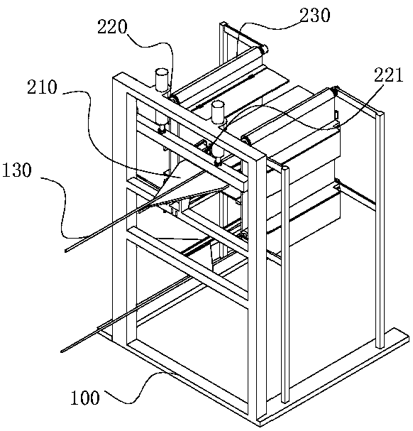
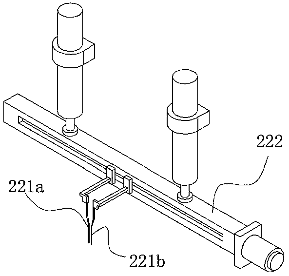
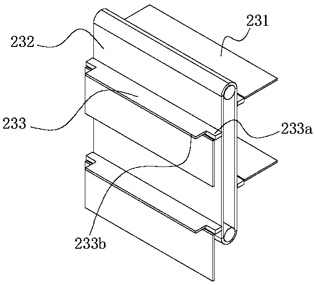
[0033] refer to Figure 4-7 , a continuous fiber transfer device is proposed in the embodiment of the present invention, comprising a frame 100, a discharge device 200 is installed on the frame 100, a supporting surface 231a is provided on the discharging device 200, and the supporting surface 231a is used for For lifting fibers, the supporting surface 231a is provided with an area for the conveying device 130 to pass through, and the middle part of the fiber is suspended in the area where the conveying device 130 passes. 330 and transfer mechanism 310. The lifting mechanism 330 is used to lift the carrier 340. During the movement of the carrier 340 from bottom to top, it lifts up the suspended fiber body in the middle, and the carrier 340 can pass through the suspended area of ​​the fiber body. The transfer mechanism 310 drives the carrier 340 away from the unloading device 200 and transfers it to the next process.

[0034] The projected length of the bearing part 340 on the...

Embodiment 2

[0057] refer to Figure 1-7 , a fiber continuous unloading device, including a frame 100, a conveying device 130 is arranged on the frame 100, the conveying device 130 is used to convey fibers, the middle part of the fiber is set on the conveying device 130, and the two ends are suspended downwards Arrangement; the frame 100 is provided with a moving mechanism 230, the moving mechanism 230 is connected to the supporting surface, the moving mechanism 230 can drive the supporting surface to move from the bottom of the conveying device 130 to the top of the conveying device 130, and the supporting surface is from below the conveying device 130 to During the movement above the conveying device 130 , the supporting surface contacts and holds up the suspension section of the fiber, and the fiber is taken out from the conveying device 130 , and the supporting surface is provided with an area for the conveying device 130 to pass through.

[0058] The supporting surface is arranged at ...


PUM


Abstract

The invention relates to a continuous material transfer device of a fiber. The continuous material transfer device of the fiber comprises a machine frame, wherein a discharging device is arranged on the machine frame; a supporting surface is arranged on the discharging device; the supporting surface is used for lifting the fiber; an area for a conveying device to penetrate through is arranged on the supporting surface; the middle part of the fiber is suspended in the area for the conveying device to penetrate through; two sections of material bodies are erected on the supporting surface; a lifting mechanism and a transfer mechanism are arranged on the machine frame; the lifting mechanism is used for lifting a bearing piece; and during the movement of the bearing piece from bottom to top, the suspended material bodies in the middle of the fiber are supported, the bearing piece can penetrate through the suspended area of the material bodies of the fiber, the transfer mechanism drives thebearing piece to be far away from the discharging device, and the bearing piece is transferred to the next process. The continuous material transfer device of the fiber is reasonable in structure, stable in movement, capable of realizing the material transfer movement of the fiber, capable of realizing automatic and continuous material transfer work, high in material transfer efficiency and capable of meeting the current use requirements.

Description

technical field [0001] The invention relates to the field of fiber processing, in particular to a continuous fiber transfer device. Background technique [0002] In animals and plants, fibers play an important role in maintaining tissues. Fibers are widely used and can be woven into thin threads, thread ends and hemp ropes, and can also be woven into fiber layers when making paper or felt. They are also commonly used to make other materials and form composite materials with other materials. [0003] When making processed fibers, more and more assembly line automation equipment is used, but it is more troublesome to transfer materials from the assembly line conveying device. This kind of work is generally carried out manually, which cannot meet the current use requirements. Contents of the invention [0004] The object of the present invention is to provide a continuous fiber transfer device for transferring fiber materials to the next process. [0005] The technical sche...

Claims


Application Information

Patent Timeline
Patent Type & Authority Applications(China)
IPC IPC(8): B65G47/34B65G15/58
Inventor 王婷朱菲刘先龙程茂根孙征
Owner 岳西十行机械设备有限公司
Why Eureka
Try Eureka