Sounding pipe parallel limiting device

The technology of a limit device and acoustic tube is applied in the direction of basic structure testing, construction, and basic structure engineering. It can solve the problems of complex parallel limit devices, reduce concrete pouring efficiency, and detect signal distortion, so as to reduce costs and The effect of construction complexity, saving raw materials and material resources and manpower, and improving service life

Inactive Publication Date: 2019-05-07
CHINA ELECTRIC POWER RES INST +1
View PDF5 Cites 4 Cited by
  • Summary
  • Abstract
  • Description
  • Claims
  • Application Information

AI Technical Summary

Problems solved by technology

Since welding may burn through the acoustic measuring tube or form weld bumps on the inner wall of the tube, affecting the straightness of the acoustic measuring tube or even leaking slurry, it has been seldom used now; The pipes are parallel and equidistant, which makes it difficult to analyze the detection data of the concrete pile by the acoustic transmission method, which may lead to misjudgment or missed judgment
[0003] The patent document of publication number CN104374832A provides a kind of solution for solving the above-mentioned problem, comprises two sleeves and the limit bar that connects two sleeves; The sleeve limit rod between the two pipes is made of steel, and the detection area of ​​the acoustic wave transmission method is the concrete quality between the two pipes. The propagation characteristics of the sound wave in the steel are different from those in the concrete, which may cause the detection signal to be distorted; 2) Specification requirements The sound measuring tubes are arranged in a symmetrical shape inside the steel cage, and there can be 2, 3 or more tubes according to the diameter of the pile. The limit rod of this solution will pass through the center of the steel cage for the arrangement of 2 tubes, and place the steel cage horizontally. Section cut into 2 parts, 3 tubes arrangement Cut the reinforcement cage cross section into 4 small parts, smaller triangular area
When pouring concrete, the above arrangement of acoustic measuring tubes will restrict the spatial arrangement of concrete conduits or chutes and the free movement of concrete vibrating rods, reducing the efficiency of concrete pouring; 3) The entire parallel limiting device is relatively complicated and only considers The spatial positional relationship between the tubes, the spatial positional relationship between the acoustic tube and the main body of the steel cage is not explained, and the acoustic tube and the steel cage are lowered and pre-buried together when the site construction is not realized

Method used


Image

  • Sounding pipe parallel limiting device
  • Sounding pipe parallel limiting device
  • Sounding pipe parallel limiting device

Examples


Embodiment 1

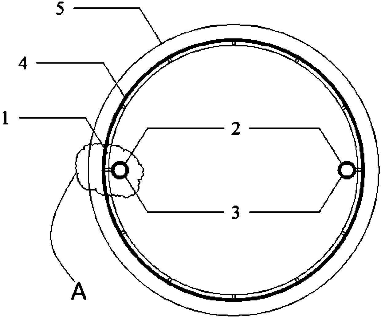
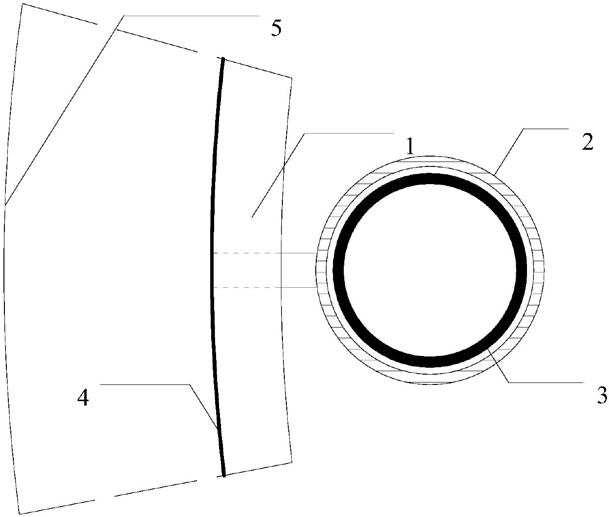
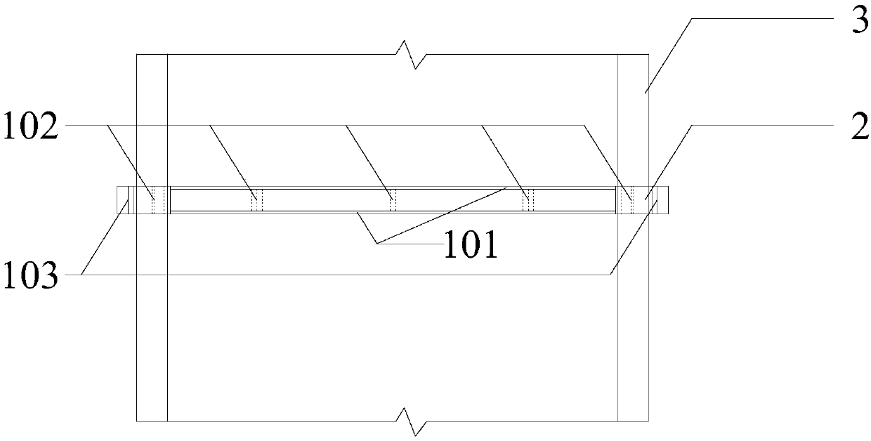
[0045] Such as image 3 and Figure 4 As shown, the parallel limiting device provided in this embodiment includes two sleeves, which are respectively arranged at both ends of a diameter of the double-layer ribbed steel ring;

[0046] The steel ring 1 is composed of the following components by mass fraction:

[0047] Li: 1.9, Cu: 1.1, Mg: 0.9, Zr: 0.08, Fe: 0.12, Si: 0.10, and the balance is Al.

[0048] The reinforcing ribs are composed of the following components by mass fraction:

[0049] C: 0.12, Si: 0.20, Mn: 0.50, P: 0.035, S: 0.050, Cu: 0.20, and the balance is iron.

[0050] The casing 2 is composed of the following components by mass fraction:

[0051] C: 1 part; N: 2 parts, In: 0.8 parts, Pd: 0.08 parts, Zr: 0.9 parts, Ir: 1 part, Rh: 1.5 parts, Fe: 40 parts.

[0052] The material design of the casing, steel ribs and steel ring in this embodiment can effectively improve its rigidity and the rigidity of the overall device after the three are connected, provide a g...

Embodiment 2

[0054] Such as Figure 5 As shown, the parallel limiting device provided in this embodiment includes three sleeves, and the three sleeves are symmetrical about the center of the double-layer ribbed steel ring;

[0055] The steel ring 1 is composed of the following components by mass fraction:

[0056] Li: 2.6, Cu: 1.6, Mg: 1.4, Zr: 0.15, Fe: 0.12, Si: 0.10, and the balance is Al.

[0057] The reinforcing ribs are composed of the following components by mass fraction:

[0058] C: 0.12, Si: 0.20, Mn: 0.50, P: 0.030, S: 0.0:40, Cu: 0.20, and the balance is iron.

[0059] The casing 2 is composed of the following components by mass fraction:

[0060] C: 1 part; N: 2 parts, In: 0.8 parts, Pd: 0.08 parts, Zr: 0.9 parts, Ir element: 1 part, Rh: 1.5 parts, Fe: 40 parts.

[0061] The material design of the sleeve, steel rib and steel ring in this embodiment can effectively improve its rigidity and the rigidity of the overall device after the three are connected, provide a guarantee f...


PUM


Abstract

The invention provides a sounding pipe parallel limiting device. Sounding pipes are connected with a reinforcement cage in a foundation pile; the steel reinforcement cage comprises vertical ribs parallel to each other, inner stirrups and outer stirrups, wherein the inner stirrups and the outer stirrups are connected with the vertical ribs. The limiting device comprises a double-layer ribbed steelring connected with the vertical ribs and vertical sleeves arranged on the inner side of the steel ring at equal intervals. The sleeves are used for accommodating the sounding pipes. According to thetechnical scheme provided by the invention, by adopting the double-layer ribbed steel ring and the vertical sleeves arranged on the inner side of the double-layer ribbed steel ring, the requirementsof parallel and equidistant installation of the sounding pipes can be met; and the limiting device is annular, enough space is reserved for concrete pouring and vibrating in the center, and detectionsignals cannot be affected. The parallel limiting device is simple in structure and convenient to apply, and can replace the effect of inner stirrups or inner and outer stirrups in reinforcement cagemanufacturing, so that raw materials and material resources and manpower of the inner stirrups are saved, and the cost and the construction complexity are reduced while the performance is improved.

Description

technical field [0001] The invention relates to an installation device for an acoustic measuring tube, in particular to a parallel limiting device for an acoustic measuring tube. Background technique [0002] In the foundation construction of buildings or structures, the sound wave transmission method is usually used to detect whether the pouring quality of the concrete pouring pile is qualified. It is necessary to pre-embed the pipe for the probe of the detection equipment to enter in the pile foundation, that is, the acoustic pipe. When the acoustic tubes are installed, the acoustic tubes along the pile body should be parallel to each other, and the distance between every two adjacent tubes should be the same. In the prior art, the general practice is to directly bind or weld the steel sound measuring tubes on the inner side of the reinforcement cage. Since welding may burn through the acoustic measuring tube or form weld bumps on the inner wall of the tube, affecting the...

Claims


Application Information

Patent Timeline
Patent Type & Authority Applications(China)
IPC IPC(8): E02D33/00
Inventor 赵江涛刘佳龙刘华清王宝齐贺雷张琰冯自霞
Owner CHINA ELECTRIC POWER RES INST
Why Eureka
Try Eureka