
A split smart plunger with a pulley mechanism

A split type, pulley technology, applied in the fields of mining fluids, mechanical equipment, machines/engines, etc., can solve the problem of uncontrollable movement speed of the plunger, and achieve the effect of shortening the up time, increasing the control efficiency and improving the service life.

Inactive Publication Date: 2021-06-15
SOUTHWEST PETROLEUM UNIV
View PDF9 Cites 0 Cited by
  • Summary
  • Abstract
  • Description
  • Claims
  • Application Information

AI Technical Summary

Problems solved by technology

[0007] The purpose of the present invention is to solve the problem of uncontrollable plunger movement speed in actual gas well drainage, and proposes a split type intelligent plunger with pulleys, which realizes real-time control of the speed of the plunger in the process of going up and down, making it safe Smoothly reach the bottom or wellhead, avoid damage to the bottom or wellhead equipment due to excessive impact force, and reduce the risk of downhole accidents

Method used


Image

  • A split smart plunger with a pulley mechanism
  • A split smart plunger with a pulley mechanism
  • A split smart plunger with a pulley mechanism

Examples


Embodiment 1

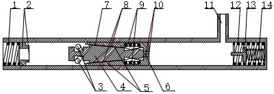
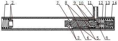
[0038] Embodiment 1: as image 3 As shown, at the top end, the plunger body (4) and the plunger sleeve (7) are thrown into the gas well as a whole.

Embodiment 2

[0039] Embodiment 2: on the basis of embodiment 1, as Figure 4 As shown, the plunger body (4) is separated from the plunger sleeve (7) under the action of the push rod of the top limiter, and then falls first.

Embodiment 3

[0040] Embodiment 3: on the basis of embodiment 2, as Figure 5 As shown, the plunger body (4) performs a free-fall motion in the wellbore until it reaches the optimal speed range calculated by the previous dynamic model.


PUM


Abstract

The invention relates to the field of gas well drainage and gas recovery, in particular to a split-type intelligent plunger with a pulley mechanism. It is characterized in that: the intelligent plunger includes the plunger body and the pulley mechanism at its lower end, the plunger sleeve and its built-in spring slips, the opening butterfly valve with locking device, the upper and lower buffers and the self-adaptive valve mechanism built in the lower buffer And the pressure, temperature, and speed sensors and microprocessor attached to the plunger body and the plunger sleeve control the speed of the plunger body and the plunger sleeve in the upward or downward process by controlling the action of the pulley mechanism. Compared with the existing technology, it has the following advantages: It solves the defect that the speed of the plunger used for drainage is uncontrollable in the continuous production operation without shutting down the well, and thus effectively avoids the plunger body and the plunger sleeve in the upward or downward process. In the process, severe collision occurs, causing downhole or wellhead accidents.

Description

technical field [0001] The invention relates to the field of gas field drainage and gas production, in particular to a split-type intelligent plunger with a pulley mechanism. Background technique [0002] According to the data of the National Energy Administration, the proportion of my country's primary energy consumption: natural gas accounted for 2.7% in 2003, increased to 5.3% in 2010, and is expected to increase to 9.8% by 2020. It can be seen from this that under the general tone of constantly emphasizing environmental protection, reducing pollution, and green mountains and green waters are golden mountains and silver mountains, my country's energy structure is constantly tilting towards cleaner energy, so my country's natural gas demand is still showing an upward trend . However, nearly 30% of my country's current natural gas consumption depends on imports from overseas. Therefore, it is very necessary to increase my country's total natural gas production to meet the n...

Claims


Application Information

Patent Timeline
Patent Type & Authority Patents(China)
IPC IPC(8): E21B43/00E21B34/06F04B47/12
Inventor 朱海燕张庆恺董润刘清友刘文全赵建国
Owner SOUTHWEST PETROLEUM UNIV
Learn More