Water injection system, ice maker and refrigerator

A technology of water injection system and refrigerator, which is applied in ice making, ice making, household refrigeration equipment, etc. It can solve the problems of water blocking water pipes and inaccurate water addition, so as to avoid high cost, no waste of space, and low cost Effect

Pending Publication Date: 2019-05-07
HAIER SMART HOME CO LTD
View PDF0 Cites 12 Cited by
  • Summary
  • Abstract
  • Description
  • Claims
  • Application Information

AI Technical Summary

Problems solved by technology

[0005] In order to solve the problem in the prior art that the amount of water added to the ice making box is inaccurate, and the water freezes and blocks the w

Method used


Image

  • Water injection system, ice maker and refrigerator
  • Water injection system, ice maker and refrigerator
  • Water injection system, ice maker and refrigerator

Examples


Embodiment 1

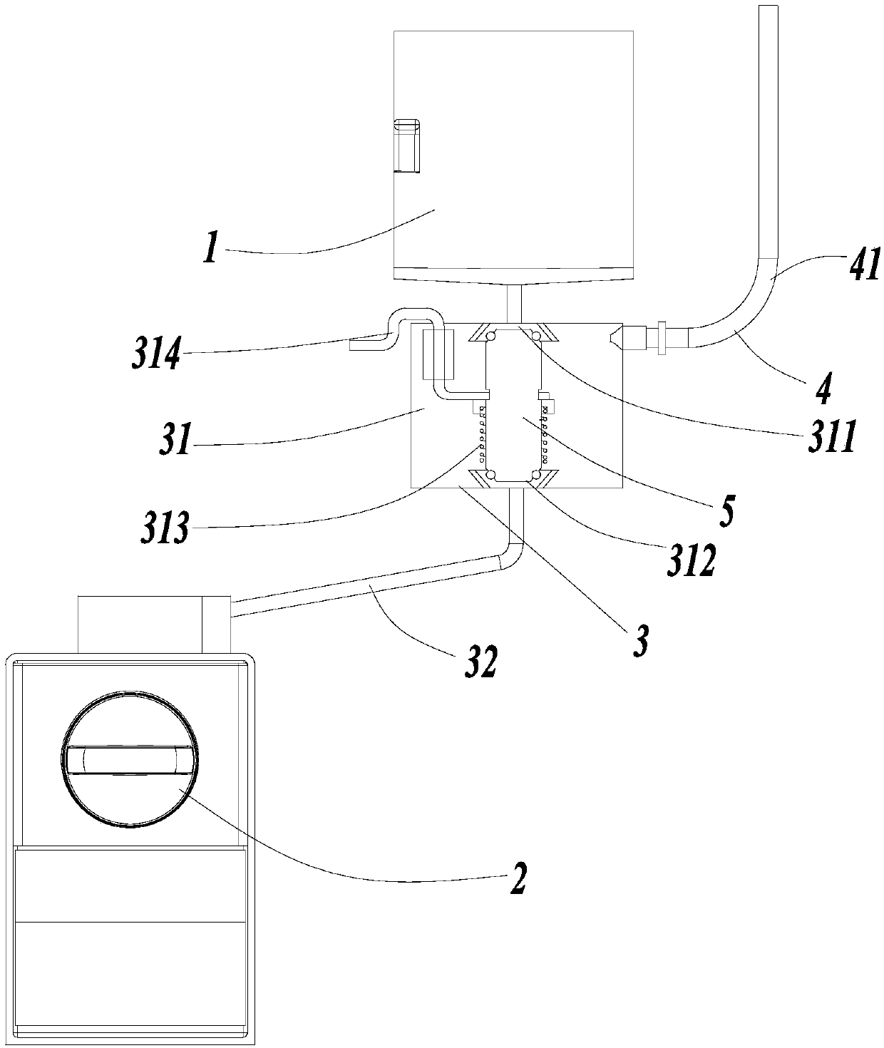
[0030] An embodiment of the present invention provides a water injection system, such as figure 1 As shown, it includes a water storage part 1 and a water demand part 2. The water storage part 1 is used to hold water, and the water demand part 2 is used to receive the water from the water storage part 1. The water storage part 1 and the water demand part 2 pass through water pipes The components 3 are connected, and the water flows from the water storage part 1 into the water demand part 2 by its own power.

[0031] In this embodiment, in order to clearly express the position and direction described in this application, roughly refer to the direction of water flow, since water flows from the water storage part 1 into the water demand part 2 by gravity, so spatially, the upstream direction defines Up and downstream are defined as down, that is, the water storage part 1 is arranged above the water pipe assembly 3 , and the water demand part 2 is arranged below the water pipe ass...

Embodiment 2

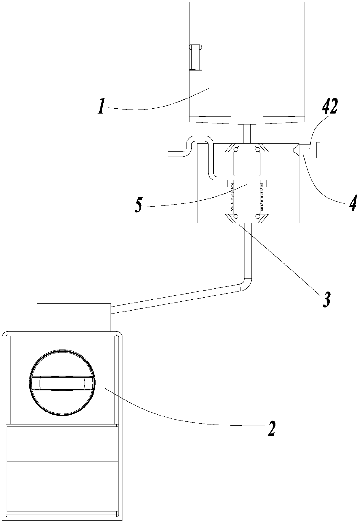
[0050] ginseng figure 2 Another embodiment is provided, and the same reference numerals used in this embodiment as in Embodiment 1 mean structures / components with similar or identical features. The only difference between this embodiment and Embodiment 1 is that the structure of the emptying part 4 is changed. This difference will be introduced in detail below, and other parts that are the same as those in Embodiment 1 will not be repeated here.

[0051] In this embodiment, the air pipe 41 in Embodiment 1 is changed to a one-way valve 42 in view of the state that the water in the water storage part 1 is an external water source, that is, the water storage part 1 is directly connected to the water outlet device with pressure. The one-way valve 42 controls the external air to enter the water flow channel through the air flow channel in one direction, so as to prevent water from flowing into the air flow channel from the water flow channel and overflowing from the emptying part...

Embodiment 3

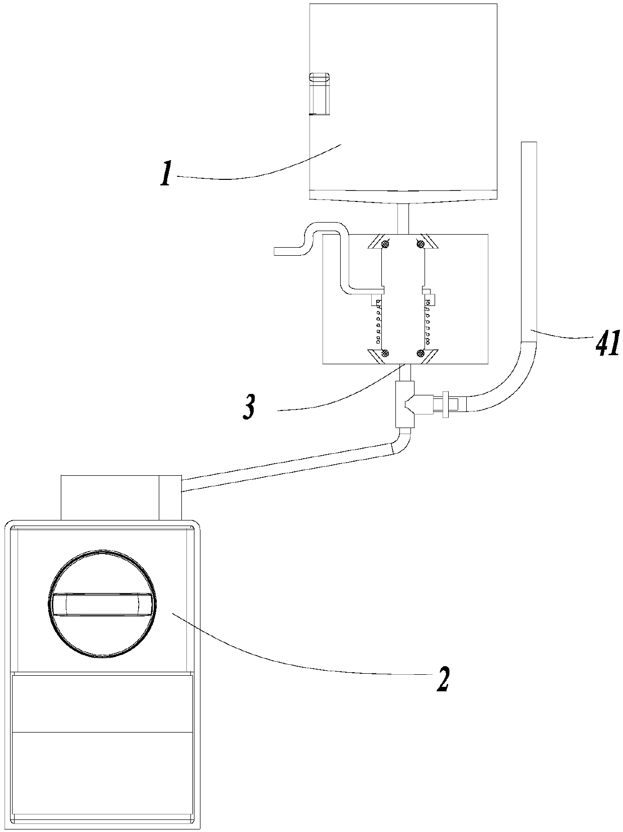
[0055] ginseng image 3 Another embodiment is provided, and the same reference numerals used in this embodiment as in Embodiment 1 mean structures / components with similar or identical features. The only difference between this embodiment and Embodiment 1 is that the position of the emptying part 4 is changed. This difference will be introduced in detail below, and other parts that are the same as those in Embodiment 1 will not be repeated here.

[0056] In this embodiment, the emptying part 4 is arranged on the first water pipe 32 , and the emptying part 4 includes a ventilation pipe 41 . The water in the water storage part 1 is in the state of holding water, that is, the water flows downward under the effect of its own gravity. At this time, the end of the vent pipe 41 is higher than the highest liquid level of the water in the quantitative part 31, so as to prevent the quantitative part from The water in 31 overflows from the air vent. When the water injection system is ap...


PUM


Abstract

The invention discloses a water injection system, an ice maker and a refrigerator. The water injection system comprises a water storage part, a water requiring part, a water pipe assembly, a water valve and an emptying part; a waterflow channel located between the water storage part and the water requiring part is defined by the water pipe assembly; the water valve is arranged on the water pipe assembly and controls water discharging of the water storage part; the emptying part is arranged on the water pipe assembly and located above the water requiring part and comprises an airflow channel enabling the waterflow channel to communicate with the outside world, the waterflow channel communicates with the water requiring part through the waterflow channel, and water in the position, located between the emptying part and the water requiring part, of the interior of the waterflow channel completely flows into the water requiring part. Air pressure of the interior of the water injection system is balanced through the emptying part, water in the water pipe assembly is emptied in time, and the situation that water freezes in a water pipe assembly, a pipe is blocked, and electric heating wires are used is avoided. According to the scheme, the cost is low, no space is wasted, the implementation method is simple and reliable, and the water injection system can be applied to an external water source or the condition that water flows on the basis of gravity.

Description

technical field [0001] The invention relates to a water injection system, in particular to an ice maker and a refrigerator with the water injection system. Background technique [0002] At present, the ice making box is usually placed in the refrigerator to make ice, but filling the ice making box with water has always been a difficult point in the ice making system. The current existing scheme is to place the ice making box in the freezing chamber, and add water to the ice making box from the outside, which eliminates the inconvenience of water splashing inside when the ice making box is put into the refrigerator. [0003] At present, in the process of adding water to the ice making box, a certain amount of water flows into the ice making box by connecting an external water source and configuring a sensor and a solenoid valve, but the cost is high, and when adding water manually, the amount of water added cannot be accurate Control, there is a problem that too little water...

Claims


Application Information

Patent Timeline
IPC IPC(8): F25C1/24F25D23/12
Inventor 崔船张延庆薛建军阳军左立华杜启海
Owner HAIER SMART HOME CO LTD
Why Eureka
Try Eureka