A non-contact torque measuring device with variable speed function

A non-contact, torque measurement technology, used in measurement devices, torque measurement, power measurement, etc., can solve the problems of cumbersome mechanical alignment, easy damage to strain gauges, easy fatigue damage, etc., and achieves simple and convenient installation and maintenance. No need for lubrication and cooling, the effect of preventing mechanical damage

Active Publication Date: 2021-05-04
INST OF ELECTRICAL ENG CHINESE ACAD OF SCI
View PDF13 Cites 0 Cited by
  • Summary
  • Abstract
  • Description
  • Claims
  • Application Information

AI Technical Summary

Problems solved by technology

[0002] At present, most torque measuring devices measure the torque by measuring the strain of the strain gauge, so the measuring equipment is installed between the driving end and the driven end, which is difficult to install in many narrow places; On the one hand, good mechanical centering is required, otherwise, it is easy to cause damage to the device under test or the measuring device during high-speed rotation, and the mechanical centering is cumbersome and time-consuming
At the same time, the strain gauge used for torque measurement is easily damaged by external force or harsh environment, and it is difficult to repair
In many measurement test benches, gearboxes are required for speed change, while mechanical gearboxes require lubrication and cooling, long-term use requires maintenance, and are prone to fatigue damage

Method used


Image

  • A non-contact torque measuring device with variable speed function
  • A non-contact torque measuring device with variable speed function
  • A non-contact torque measuring device with variable speed function

Examples


Embodiment 1

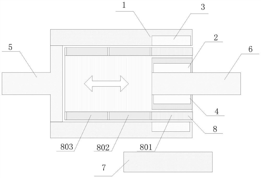
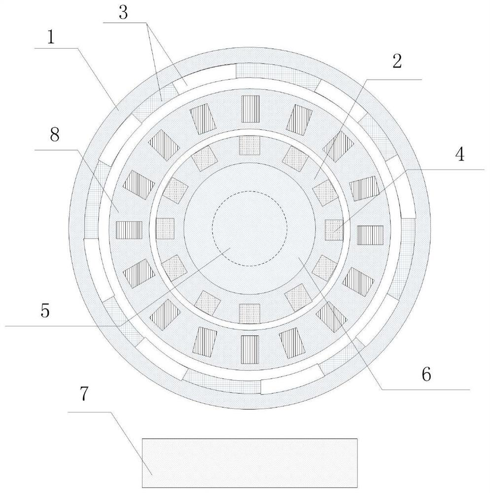
[0054] Such as figure 1 , figure 2 , Image 6 with Figure 7As shown, a non-contact torque measurement device with variable speed function, the measurement device includes: a measurement module 7, a permanent magnet rotor, a squirrel cage rotor, a magnetic field modulation ring 8, a driving end 5 and a driven end 6;

[0055] The permanent magnet rotor is connected to the driving end 5, the squirrel cage rotor is connected to the driven end 6, and the torque change of the permanent magnet rotor is transmitted to the squirrel cage rotor;

[0056] The permanent magnet rotor, the magnetic field modulation ring 8 and the squirrel cage rotor are sequentially nested from outside to inside and fixed on the same axis;

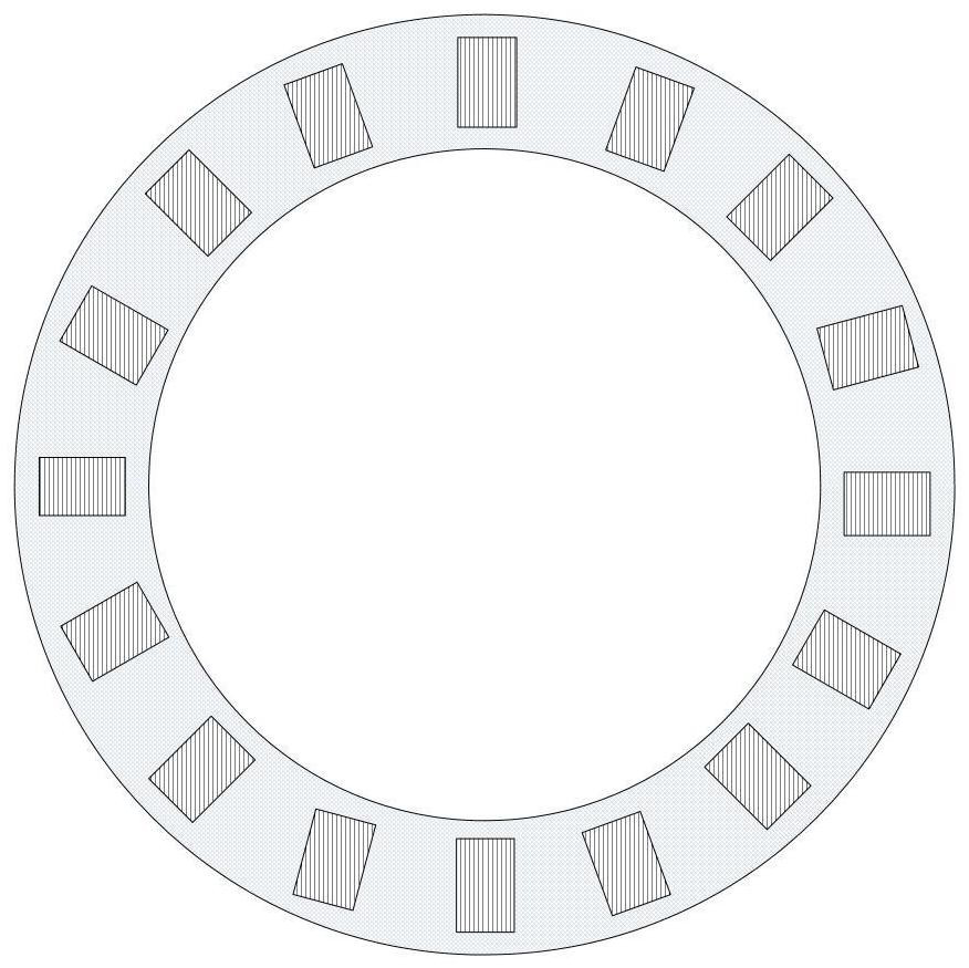
[0057] The magnetic field modulation ring includes a multi-section modulation iron core, the multi-section modulation iron cores are placed side by side, the multi-section modulation iron cores are all provided with slots, and the slot numbers of the multi-section m...

Embodiment 2

[0080] Figure 8 It shows a non-contact torque measuring device with variable speed function according to the second embodiment of the present invention, the torque measuring device includes a permanent magnet rotor, a magnetic field modulation ring 8 and a squirrel cage rotor, the squirrel cage rotor is a cylindrical structure and The inner diameter of the squirrel cage rotor is greater than the outer diameter of the magnetic field modulation ring 8, and the inner diameter of the magnetic field modulation ring 8 is greater than the outer diameter of the permanent magnet rotor; the permanent magnet rotor is composed of a permanent magnet rotor core 1 and a permanent magnet 3, and the permanent magnet core 1 can be composed of Silicon steel sheets or other soft magnetic materials are stacked to form a cylindrical structure, which can also be made of magnetically conductive materials such as amorphous. The N and S poles of the permanent magnet 3 face the center of the circle, and...


PUM


Abstract

The invention discloses a non-contact torque measuring device with variable speed function. The measuring device comprises: a measuring module, a permanent magnet rotor, a squirrel cage rotor, a magnetic field modulation ring, a driving end and a driven end; the permanent magnet The rotor is connected to the driving end, the squirrel cage rotor is connected to the driven end, and the torque of the permanent magnet rotor is transmitted to the squirrel cage rotor; the permanent magnet rotor, the magnetic field modulation ring and the The squirrel-cage rotors are nested sequentially from outside to inside and installed concentrically; the measurement modules are wirelessly connected to the permanent magnet rotor and the squirrel-cage rotor respectively, and the measurement modules are used to measure the permanent magnet rotor and the squirrel-cage rotor. The rotational speed of the squirrel cage rotor, and calculate the torque between the permanent magnet rotor and the squirrel cage rotor according to the rotational speed and torque transfer ratio of the permanent magnet rotor and the squirrel cage rotor. It can realize stepped speed regulation, integrates the speed change function, coupling function and torque measurement together, has no maximum speed restriction, and can realize high-speed operation.

Description

technical field [0001] The invention relates to the field of torque measuring devices, in particular to a non-contact torque measuring device with a speed changing function. Background technique [0002] At present, most torque measuring devices measure the torque by measuring the strain of the strain gauge, so the measuring equipment is installed between the driving end and the driven end, which is difficult to install in many narrow places; On the one hand, a good mechanical centering is required, otherwise, it is easy to cause damage to the device under test or the measuring device during high-speed rotation, and the mechanical centering is cumbersome and time-consuming. At the same time, the strain gauge used for torque measurement is easily damaged by external force or harsh environment, and it is difficult to repair. In many measurement test benches, gearboxes are required for speed change, while mechanical gearboxes require lubrication and cooling, require maintenanc...

Claims


Application Information

Patent Timeline
Patent Type & Authority Patents(China)
IPC IPC(8): G01L3/10
Inventor 赵峰郭柯
Owner INST OF ELECTRICAL ENG CHINESE ACAD OF SCI
Why Eureka
Try Eureka