A method and device for measuring and calculating the exit angle of Tamm coupling based on excitation registration

An exit angle and registration technology, which is used in measurement devices, material excitation analysis, and optical devices, etc., can solve the problems of low efficiency, difficult to identify the exit angle, and low universality.

Active Publication Date: 2021-07-06
NANJING UNIV OF SCI & TECH
View PDF0 Cites 0 Cited by
  • Summary
  • Abstract
  • Description
  • Claims
  • Application Information

AI Technical Summary

Problems solved by technology

Difficult to measure pulsed and complex spot distributions
At the same time, the noise of the illumination field of view, the offset of the CCD target surface, and the aberration of the imaging lens are all likely to cause errors
Need to shape the beam, which limits the scope of application
(2) Slow speed
Conventional exit angle determination often needs to rotate the mechanical device, which is slow, inefficient, and unstable factors such as backstroke difference exist at the same time
(3) Low resolution
Using traditional CCD measurement, even if the speed has been improved, it is difficult to achieve high measurement resolution due to the limitation of pixel size when measuring small beams. At the same time, it is affected by light intensity changes and drift, which reduces the actual measurement accuracy.
In the face of special light spots, there will be dead zones that cannot be detected
For special spots, the divergence angle may not be evenly distributed, so the measurement control range is small
(4) Low universality. Existing methods using quadrants or microscopic imaging can only measure simple exiting light angles, and it is difficult to identify the exiting angles of complex structures, and there are many precision optical mechanical components, which are expensive and time-consuming Long

Method used


Image

  • A method and device for measuring and calculating the exit angle of Tamm coupling based on excitation registration
  • A method and device for measuring and calculating the exit angle of Tamm coupling based on excitation registration
  • A method and device for measuring and calculating the exit angle of Tamm coupling based on excitation registration

Examples


Embodiment Construction

[0029] Below in conjunction with accompanying drawing of description, the present invention will be further described.

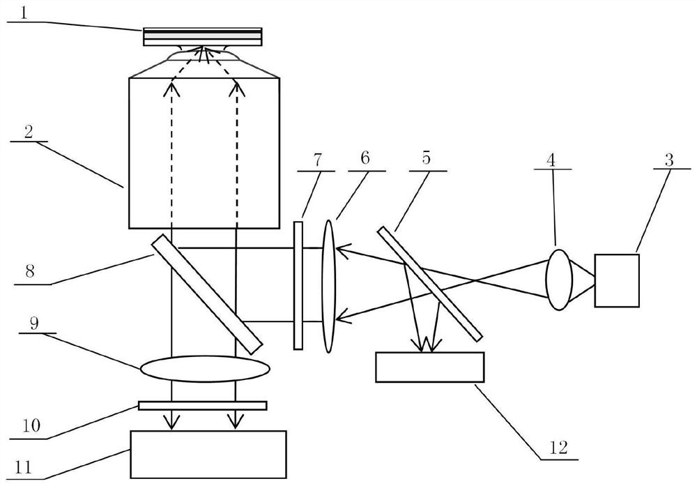
[0030] combine figure 1 , a Tam coupling exit angle measurement device based on excitation registration, said device includes a Tam structure 1, an oil immersion objective lens 2, a white light source 3, a converging convex lens 4, a beam splitter 5, a collimating convex lens 6, a short-wave Narrowband filter 7, dichroic mirror 8, imaging lens 9, long-wave narrowband filter 10, fluorescent CCD image sensor 11, white light CCD image sensor 12, the Tam structure 1, oil immersion objective lens 2, dichroic mirror 8 , an imaging lens 9, a long-wave narrow-band filter 10, and a fluorescent CCD image sensor 11 are arranged in sequence, the white light source 3, a focusing convex lens 4, a beam splitter 5, a collimating convex lens 6, a short-wave narrow-band filter 7, and a dichroic mirror 8 are arranged in sequence, the Tam structure 1 is located on the oil imme...


PUM

PropertyMeasurementUnit
wavelengthaaaaaaaaaa

Abstract

The invention discloses a method and device for measuring and calculating the exit angle of Tamm coupling based on excitation registration, comprising: a Tamm structure, an oil-immersion objective lens, a white light source, a converging convex lens, a beam splitter, a collimating convex lens, and a short-wave narrowband filter , Dichroic mirror, imaging lens, long-wave narrowband filter, fluorescent CCD image sensor, white light CCD image sensor. The TAM structure is placed on the top of the oil immersion objective lens, and is excited by the converging, collimated and filtered white light source, and then the excitation light is reflected back to the beam splitter by the dichroic mirror, and finally collected by the white light CCD image sensor. At the same time, the fluorescence emitted by the Tam structure is collected by the oil immersion objective lens, passes through the dichroic mirror and the long-wave narrow-band filter, and is imaged by the imaging lens on the fluorescent CCD image sensor. Using the surface wave modes of different wavelengths of light collected by two CCD image sensors to select effective feature points, realize image registration, and complete the measurement and calculation of fluorescence emission angles under high signal-to-noise ratios. The invention has simple structure and strong practicability.

Description

technical field [0001] The invention relates to the field of measurement and calculation of micro-optoelectronics, in particular to a method and device for measuring and calculating a Tam coupling exit angle based on excitation registration. Background technique [0002] In the field of research and development of integrated optical devices, due to technological innovations such as nano-quantum structures, photonic crystals, and micro-resonators, as well as the continuous development of miniaturization of micro-cavity lasers, nano-optical waveguides, and nano-optical detectors, smaller devices, more compact The integrated and lower-cost processing technology has a very wide range of applications in disciplines such as silicon-based optoelectronics, and occupies a key technology in many core technologies such as sensing, display, and detection. Therefore, micro-nano-scale optoelectronic element detection Devices have been successfully developed recently. The processing on th...

Claims


Application Information

Patent Timeline
Patent Type & Authority Patents(China)
IPC IPC(8): G01N21/64G01N21/84G01B11/26
Inventor 陈漪恺朱时军周芊江沈中华
Owner NANJING UNIV OF SCI & TECH
Why Eureka
Try Eureka