
A drainage pipe network design optimization system and method based on a GIS technology

A technology for drainage pipe network and pipe network, applied in the direction of calculation, structured data retrieval, instruments, etc., can solve the problems of pipe network data analysis and optimization, unintuitiveness, neglecting the dynamic nature of the planning process and the long-term influence of the implementation process, etc. Design optimization levels, simplify analysis and optimization methods, and improve work efficiency

Pending Publication Date: 2019-05-07
MCC CAPITAL ENGINEERING & RESEARCH
View PDF9 Cites 12 Cited by
  • Summary
  • Abstract
  • Description
  • Claims
  • Application Information

AI Technical Summary

Problems solved by technology

At present, municipal drainage pipe network information systems have been developed and established in many places in my country. However, many of these systems have the following disadvantages: Although many systems have introduced geographic information system (GIS) technology, they have realized editing, browsing, and querying of pipe network data. , statistical analysis and output functions, but many systems focus on the visual display of the entire drainage network scheme, failing to consider the analysis and optimization of the entire pipeline network data
In addition, the traditional municipal drainage network design and planning is short-term and static, ignoring the dynamic nature of the planning process and the long-term impact of planning on the implementation process
Many municipal drainage pipe network planning systems have the problem of separation of pipe hydraulic calculation and scheme design drawing, which is inconvenient and not intuitive for the design of new drainage pipe network, expansion and evaluation of existing old pipe network

Method used


Image

  • A drainage pipe network design optimization system and method based on a GIS technology
  • A drainage pipe network design optimization system and method based on a GIS technology
  • A drainage pipe network design optimization system and method based on a GIS technology

Examples


Embodiment Construction

[0047] The following will clearly and completely describe the technical solutions in the embodiments of the present invention with reference to the accompanying drawings in the embodiments of the present invention. Obviously, the described embodiments are only some, not all, embodiments of the present invention. Based on the embodiments of the present invention, all other embodiments obtained by persons of ordinary skill in the art without making creative efforts belong to the protection scope of the present invention.

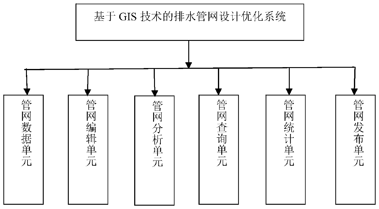
[0048] Such as figure 1 As shown, according to one aspect of the present invention, this embodiment discloses a design optimization system for drainage pipe network. In this embodiment, the system includes a pipe network data unit 11 , a pipe network editing unit 12 and a pipe network analysis unit 13 . Wherein, the pipe network data unit 11 is used to store and visualize the pipe network data of the drainage pipe network, the pipe network editing unit 12 is ...


PUM


Abstract

The invention provides a drainage pipe network design optimization system and method based on the GIS technology. The drainage pipe network design optimization system comprises a pipe network data unit, a pipe network editing unit and a pipe network analysis unit. The pipe network data unit is used for storing pipe network data of the drainage pipe network; The pipe network editing unit is used for visualizing and managing the pipe network data of the pipe network data unit; The pipe network analysis unit is used for analyzing attribute characteristics of a pipe network according to the pipe network data and carrying out pipe network hydraulic analysis, rainwater pipe network waterlogging-prone area analysis, rainwater regulation and storage pool position selection and rainwater regulationand storage pool volume determination according to the attribute characteristics of the pipe network,. various kinds of analysis and dynamic optimization design of the drainage pipe network are achieved through the geographic information technology, and the design efficiency and quality of the drainage pipe network are improved.

Description

technical field [0001] The invention relates to the technical field of municipal drainage network design, in particular to a drainage network design optimization system and method. Background technique [0002] With the rapid development of the national economy, the pace of urban construction continues to accelerate. In the design and planning process of the municipal drainage network, higher requirements are put forward for the reliability of the design results of the municipal drainage network and the water delivery capacity. [0003] Geographic information system technology is a comprehensive technology that integrates storage, query, analysis and display of geographic data. In recent years, it has been gradually applied in many fields such as urban planning, land management and underground pipe network facility management. Especially with the development of pipe network hydraulic simulation technology, in order to quickly and accurately construct pipe network information...

Claims


Application Information

Patent Timeline
Patent Type & Authority Applications(China)
IPC IPC(8): G06F16/29G06Q50/26
Inventor 李楠饶雪峰张晓磊梁思懿
Owner MCC CAPITAL ENGINEERING & RESEARCH
Learn More