
Wireless sensor

A wireless sensor and wireless module technology, applied in instruments, signal transmission systems, measuring devices, etc., can solve problems such as inconvenient on-site maintenance and fault judgment, performance degradation of power management circuits, damage to the reliability of wireless sensors, etc., to facilitate production. and on-site maintenance, easy fault diagnosis, on-site construction and maintenance convenience

Pending Publication Date: 2019-05-07
TIANDI SCI & TECH CO LTD
View PDF0 Cites 0 Cited by
  • Summary
  • Abstract
  • Description
  • Claims
  • Application Information

AI Technical Summary

Problems solved by technology

In the actual product production practice, when the wireless sensor is frequently powered on and tested, the performance of the power management circuit is significantly reduced, resulting in damage to the reliability of the wireless sensor
At the same time, in order to meet the production needs, it is often necessary to replace different types of wireless modules, so that the underlying software interface must be modified, so it brings inconvenience to on-site maintenance and fault judgment

Method used


Image

  • Wireless sensor
  • Wireless sensor
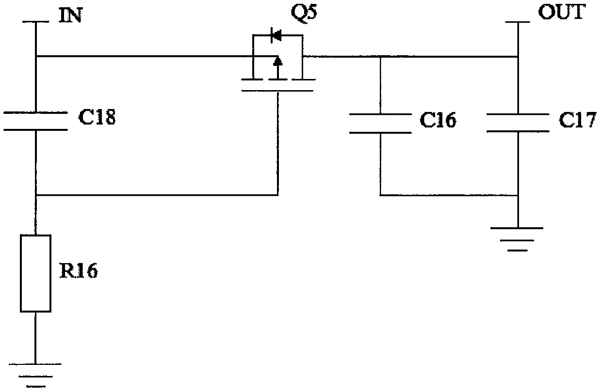
  • Wireless sensor

Examples


Embodiment Construction

[0021] In order to make the objectives, technical solutions, and advantages of the present invention clearer, the following further describes the embodiments of the present invention in detail with reference to the accompanying drawings.

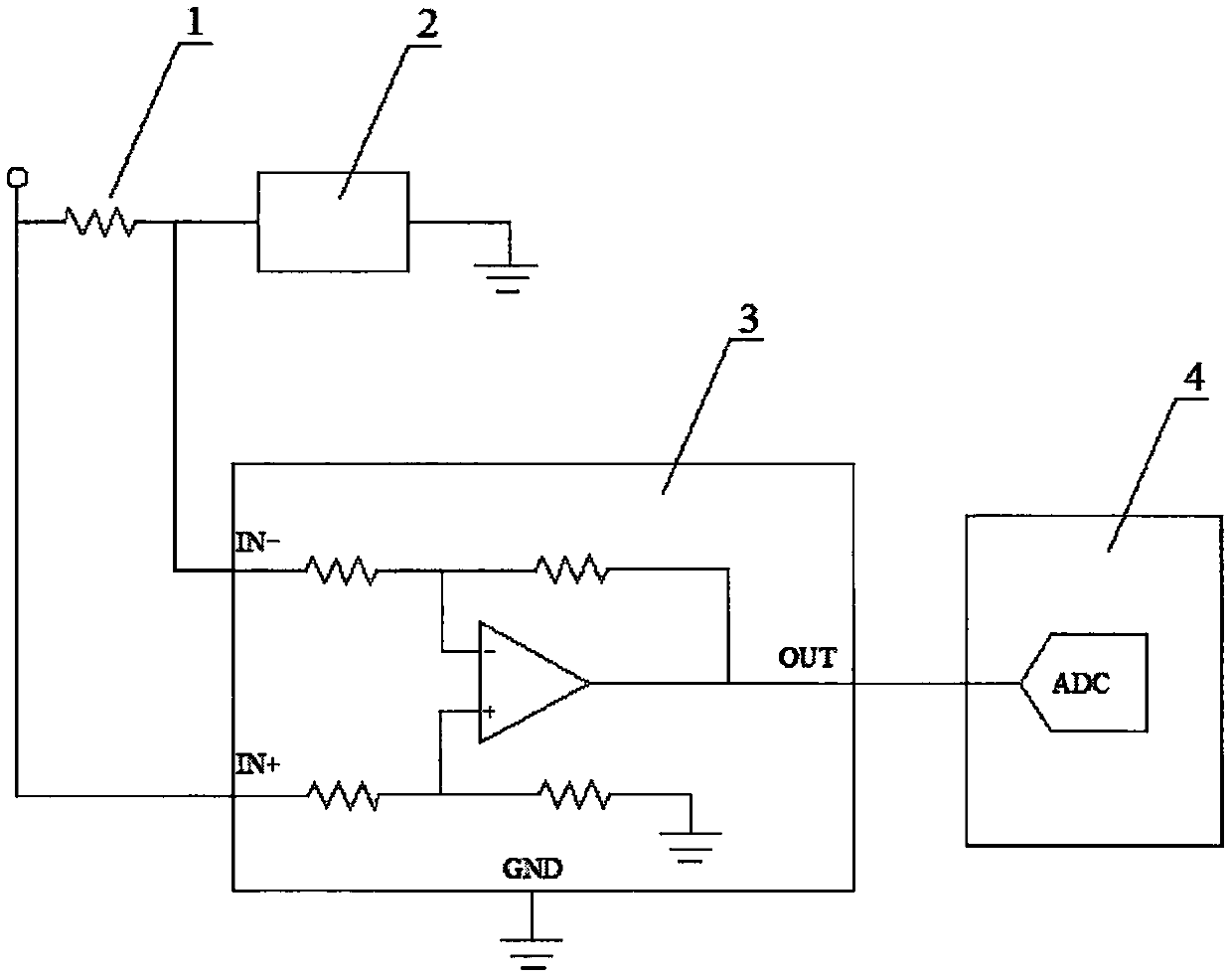
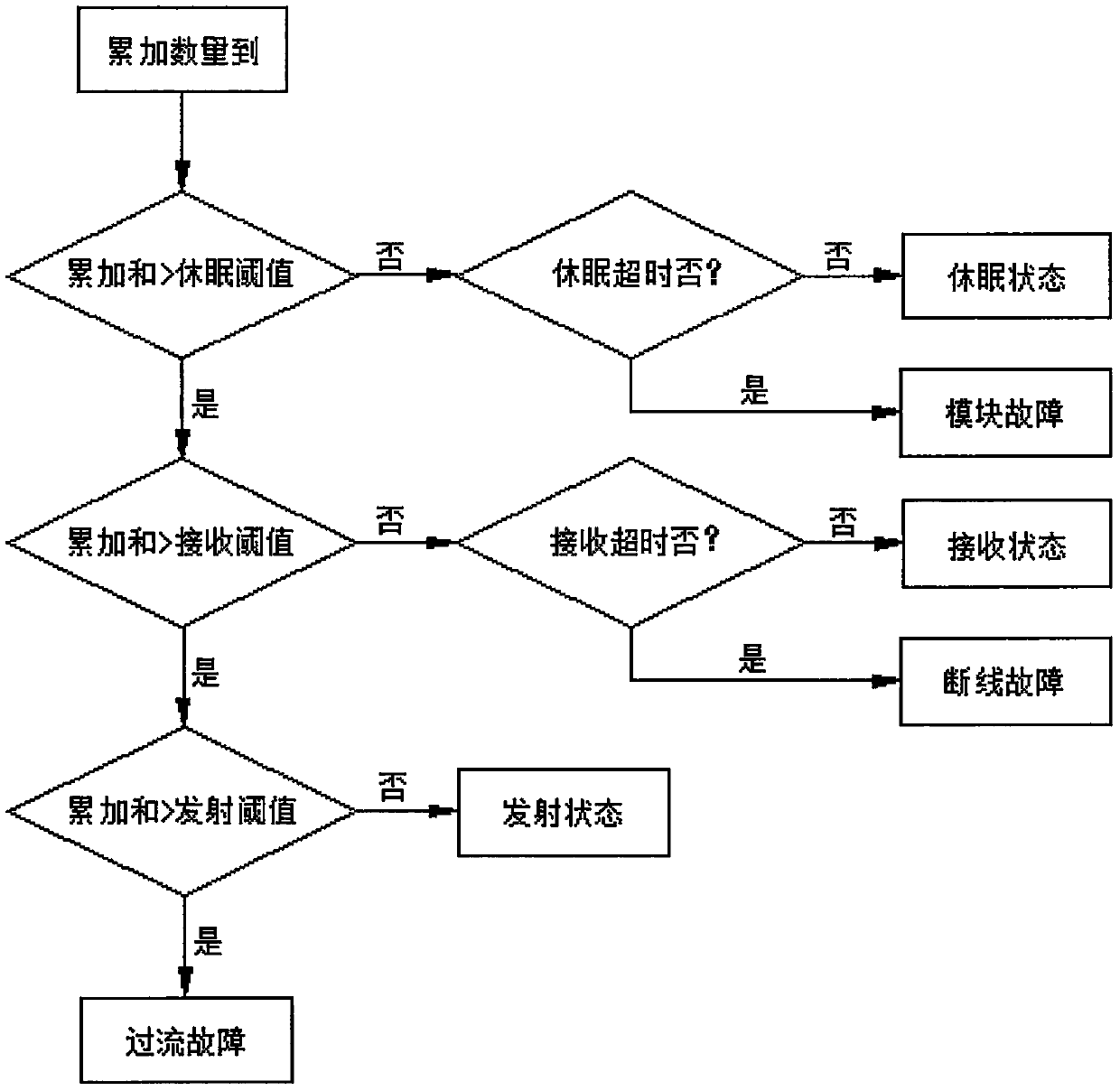
[0022] Such as Figure 1-3 Shown is a preferred embodiment of a wireless sensor of the present invention.

[0023] The wireless sensor includes a sensing module, a wireless module 2, a core processing circuit 4 and a power management circuit, as well as a wireless module startup control circuit and a wireless module working current detection circuit.

[0024] The wireless module startup control circuit includes capacitors C16, C17, and C18, a resistor R16, and a transistor Q5. Under the control of the wireless module startup control circuit, when the wireless module 2 is first powered on, C18 is charged and the gate voltage of Q5 is high , Q5 is turned off, and after C18 is charged through R16 for a period of time, the gate voltage of Q5 is reduce...


PUM


Abstract

The invention discloses a wireless sensor. The wireless sensor comprises a sensing module, a wireless module (2), a core processing circuit (4), a power supply management circuit and a wireless modulestarting control circuit. The overall reliability of the wireless sensor is effectively improved.

Description

Technical field [0001] The invention relates to a wireless sensor. Background technique [0002] Existing wireless sensors generally consist of a sensor module, a core processing circuit, a wireless module and a power management circuit. The sensor module converts external physical quantities into analog electrical signals, and the core processing circuit collects the electrical signals output by the sensor module and converts them into digital signals. , And finally upload the data through the wireless module, and the power management circuit is responsible for the power management of each module. In actual product production practice, when the wireless sensor is frequently powered on for testing, the performance of the power management circuit is significantly reduced, resulting in damage to the reliability of the wireless sensor. At the same time, in order to meet production needs, it is often necessary to replace different types of wireless modules, so that the underlying so...

Claims


Application Information

Patent Timeline
Patent Type & Authority Applications(China)
IPC IPC(8): G08C17/02G01R31/00
Inventor 张辉吕华文吴志刚王正胜
Owner TIANDI SCI & TECH CO LTD
Learn More