Four-port suction cup combined antenna

A combined antenna and four-port technology, applied in the directions of antenna, antenna coupling, antenna grounding device, etc., can solve the problems of energy loss, increase the area of ​​the radio frequency system, and it is difficult to meet the system design requirements of low power consumption. The effect of performance parameters, high utilization rate of radiation area and simple structure

Active Publication Date: 2019-05-07
GUANGZHOU CREKING COMM TECH
View PDF9 Cites 1 Cited by
  • Summary
  • Abstract
  • Description
  • Claims
  • Application Information

AI Technical Summary

Problems solved by technology

[0002] In the mobile communication system and the terminal equipment covered by the wireless network, the antenna built in the transceiver equipment usually requires the miniaturization of the external dimensions of the antenna and the electrical size of the transmission line, and must match the transceiver equipment in terms of performance, so as to Obtain good electrical performance indicators; in some more complex communication module systems with multiple frequencies such as 3G, WLAN and GPS frequency bands, the system needs to work in multiple modes, and it requires the design of an additional impedance matching network before feeding into the antenna, but the impedance The matching network additionally increases the feeder design of the electronic system and increases the area of ​​the radio frequency system. At the same time, the matching network also introduces a lot of energy loss, which is difficult to meet the system design requirements of low power consumption. Therefore, the miniaturized multi-mode technology It has become one of the most important technologies in the contemporary communication module integration system to realize the miniaturized three-band antenna

Method used


Image

  • Four-port suction cup combined antenna
  • Four-port suction cup combined antenna
  • Four-port suction cup combined antenna

Examples


Embodiment Construction

[0026] The following will clearly and completely describe the technical solutions in the embodiments of the present invention with reference to the accompanying drawings in the embodiments of the present invention. Obviously, the described embodiments are only some, not all, embodiments of the present invention. Based on the embodiments of the present invention, all other embodiments obtained by persons of ordinary skill in the art without making creative efforts belong to the protection scope of the present invention.

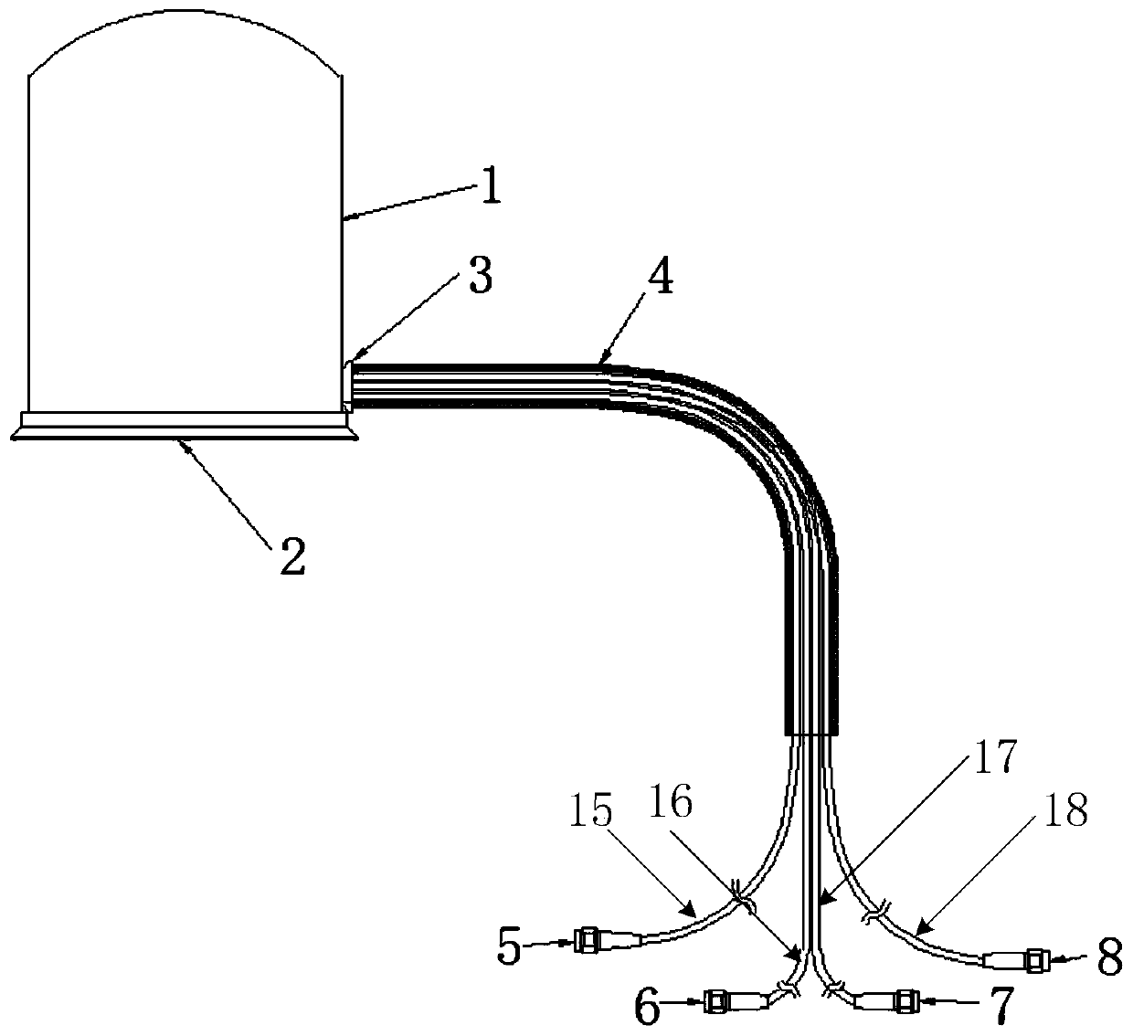
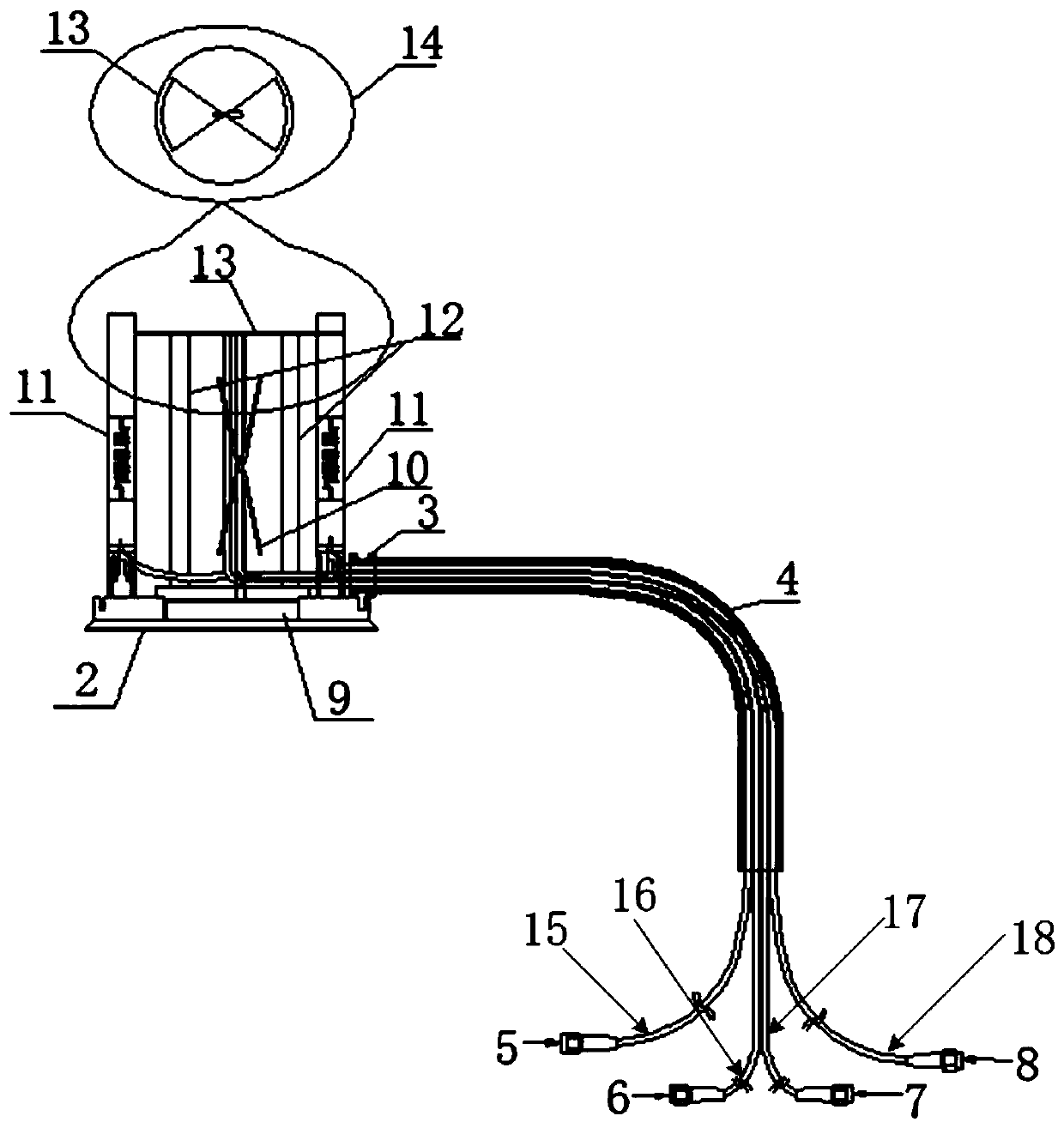
[0027] In the embodiment of the four-port suction cup combined antenna of the present invention, the structural diagram of the four-port suction cup combined antenna is as follows figure 1 As shown, the top view of the internal structure of the four-port suction cup combined antenna is as follows figure 2 shown. In this embodiment, the four-port suction cup combined antenna includes an antenna cover 1, a bottom cover 2, a wire sheath 3, a cable shield 4, a f...


PUM


Abstract

The invention discloses a four-port suction cup combined antenna. The four-port suction cup combined antenna comprises an antenna cover, a bottom cover, a retaining sleeve, a cable protector, a firstport feeding cable, a second port feeding cable, a third port feeding cable and a fourth port feeding cable. A 3G band circuit board is fixedly installed at the middle portion of the internal portionof the antenna cover, ABS support columns are respectively installed at two sides of the 3G band circuit board, one WlAN frequency circuit board is fixedly installed at the outer side of each supportcolumn, one GPS frequency circuit board is fixedly installed at the upper end of the 3G band circuit board, the GPS frequency circuit boards are fixed on a round plastic board, the two ends of the round plastic board are respectively fixedly matched with the upper end of the corresponding WlAN frequency circuit boards. The four-port suction cup combined antenna is simple in structure and small insize, can provide a good radiation performance index, and can be matched with the connection end in a transceiver device.

Description

technical field [0001] The invention relates to the field of antennas, in particular to a four-port sucker combined antenna. Background technique [0002] In the mobile communication system and the terminal equipment covered by the wireless network, the antenna built in the transceiver equipment usually requires the miniaturization of the external dimensions of the antenna and the electrical size of the transmission line, and must match the transceiver equipment in terms of performance, so as to Obtain good electrical performance indicators; in some more complex communication module systems with multiple frequencies such as 3G, WLAN and GPS frequency bands, the system needs to work in multiple modes, and it requires the design of an additional impedance matching network before feeding into the antenna, but the impedance The matching network additionally increases the feeder design of the electronic system and increases the area of ​​the radio frequency system. At the same ti...

Claims


Application Information

Patent Timeline
Patent Type & Authority Applications(China)
IPC IPC(8): H01Q1/38H01Q1/42H01Q1/48H01Q1/50H01Q1/52H01Q5/20H01Q5/30H01Q5/50
Inventor 唐江华许佐云
Owner GUANGZHOU CREKING COMM TECH
Why Eureka
Try Eureka