Winding type all-solid-state super capacitor and preparation method thereof
A supercapacitor, all-solid-state technology, used in the manufacture of hybrid/electric double-layer capacitors, hybrid boxes/casings/packages, etc., can solve the problem of high series equivalent resistance, rigidity of solid-state electrolytes that cannot be rolled, and limit the size of solid-state supercapacitors. Capacity development and other issues, to achieve the effect of improving windability, high reliability and life, and overcoming short life
- Summary
- Abstract
- Description
- Claims
- Application Information
AI Technical Summary
Problems solved by technology
Method used
Image
Examples
specific Embodiment 1
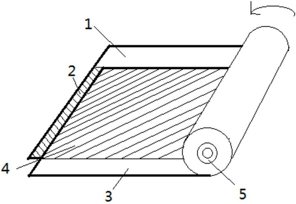
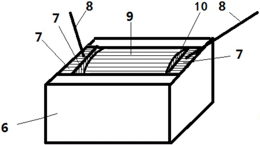
[0043] like figure 1 , figure 2 A wound-type all-solid-state supercapacitor sample AB is shown, including a bottom metal foil 1, a bottom metal foil coating 2, a top metal foil 3, a top metal foil coating 4, a winding shaft core 5, a casing 6, Conductive silver paste coating 7, electrode lead wire 8 and adhesive tape 9;
[0044] The wound supercapacitor core 10 is formed by winding the bottom metal foil 1 and the top metal foil 3 around the winding core 5 and then wrapping the tape 9. The bottom metal foil 1 is located outside the top metal foil 3, and the bottom metal foil is coated 2 is located on the upper surface of the bottom metal foil 1, and the top metal foil coating 4 is located on the upper surface of the top metal foil 3;
[0045] The top of the casing 6 is provided with a rectangular blind hole, and the winding supercapacitor core 10 is clamped in the rectangular blind hole, and the two inner sides of the rectangular blind hole corresponding to the two ends of t...
specific Embodiment 2
[0070] like figure 1 , figure 2 A wound-type all-solid-state supercapacitor is shown, including a bottom metal foil 1, a bottom metal foil coating 2, a top metal foil 3, a top metal foil coating 4, a winding shaft core 5, a casing 6, a conductive silver Slurry coating 7, electrode lead wire 8 and adhesive tape 9;
[0071] The wound supercapacitor core 10 is formed by winding the bottom metal foil 1 and the top metal foil 3 around the winding core 5 and then wrapping the tape 9. The bottom metal foil 1 is located outside the top metal foil 3, and the bottom metal foil is coated 2 is located on the upper surface of the bottom metal foil 1, and the top metal foil coating 4 is located on the upper surface of the top metal foil 3;
[0072] The top of the casing 6 is provided with a rectangular blind hole, and the winding supercapacitor core 10 is clamped in the rectangular blind hole, and the two inner sides of the rectangular blind hole corresponding to the two ends of the wind...
specific Embodiment 3
[0089] like figure 1 , figure 2A wound type all-solid supercapacitor shown, including bottom metal foil 1, bottom metal foil coating 2, top metal foil 3, top metal foil coating 4, winding shaft 5, shell 6, conductive silver Slurry coating 7, electrode lead wire 8 and tape paper 9;
[0090] The wound supercapacitor core 10 is formed by winding the bottom metal foil 1 and the top metal foil 3 around the winding core 5 and then wrapping the tape paper 9. The bottom metal foil 1 is located outside the top metal foil 3, and the bottom metal foil is coated 2 is located on the upper surface of the bottom metal foil 1, and the top metal foil coating 4 is located on the upper surface of the top metal foil 3;
[0091] The top of the casing 6 is provided with a rectangular blind hole, the wound supercapacitor core 10 is clamped in the rectangular blind hole, and the two inner sides of the rectangular blind hole corresponding to the two ends of the wound supercapacitor core 10 are prov...
PUM
| Property | Measurement | Unit |
|---|---|---|
| particle diameter | aaaaa | aaaaa |
| particle diameter | aaaaa | aaaaa |
| particle diameter | aaaaa | aaaaa |
Abstract
Description
Claims
Application Information
 - R&D
- Intellectual Property
- Life Sciences
- Materials
- Tech Scout
- Unparalleled Data Quality
- Higher Quality Content
- 60% Fewer Hallucinations
Browse by: Latest US Patents, China's latest patents, Technical Efficacy Thesaurus, Application Domain, Technology Topic, Popular Technical Reports.
© 2025 PatSnap. All rights reserved.Legal|Privacy policy|Modern Slavery Act Transparency Statement|Sitemap|About US| Contact US: help@patsnap.com


