Radiating element positioning clamp and low-frequency radiating element

A radiation unit and positioning clip technology, which is applied in the field of radiation unit positioning clips and low-frequency radiation units, can solve the problems of affecting performance indicators such as the cross-polarization ratio of the antenna, the deformation of the oscillator radiating arm cannot be corrected, and the deformation of the plastic positioning clip. , to achieve the effect of reliable fixation and deformation correction

Inactive Publication Date: 2017-12-08
GCI SCI & TECH
View PDF3 Cites 1 Cited by
  • Summary
  • Abstract
  • Description
  • Claims
  • Application Information

AI Technical Summary

Problems solved by technology

[0003] Common plastic positioning clips are open U-shaped clips, usually loaded from the side of the loading section, and snap into the positioning clip in the gap between the two radial arms in a vertical direction, and the plastic sheets at both ends of the U-shaped opening of the positioning clip are respectively stuck. The upper and lower edges of the two radiation arms are used to correct the deformation of the radiation arms. However, due to the open design of this kind of positioning clip, its structural strength and rigidity are insufficient. The deformation of the radiation arm cannot be corrected, which seriously affects the performance indicators such as the cross-polarization ratio of the antenna

Method used


Image

  • Radiating element positioning clamp and low-frequency radiating element
  • Radiating element positioning clamp and low-frequency radiating element
  • Radiating element positioning clamp and low-frequency radiating element

Examples


Embodiment Construction

[0026] The following will clearly and completely describe the technical solutions in the embodiments of the present invention with reference to the accompanying drawings in the embodiments of the present invention. Obviously, the described embodiments are only some, not all, embodiments of the present invention. Based on the embodiments of the present invention, all other embodiments obtained by persons of ordinary skill in the art without creative efforts fall within the protection scope of the present invention.

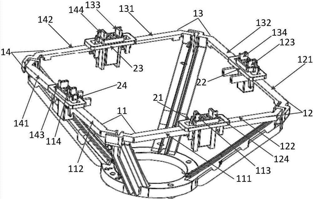
[0027] see figure 1, which is a schematic structural diagram of a low-frequency radiation unit provided by a preferred embodiment of the present invention. The embodiment of the present invention provides a low-frequency radiation unit 1, including a plurality of dipoles, each of which includes a first radiation arm and a second radiation arm, and the end of the first radiation arm is provided with a first A loading section, the end of the second radiation arm is ...


PUM


Abstract

The invention discloses a radiating element positioning clamp, which is used for connecting adjacent first radiating arm and second radiating arm which are located in different dipoles. The radiating element positioning clamp comprises a substrate, wherein the substrate is provided for a first undercut part and a second undercut part used for being clamped and fixed on the first radiating arm; the substrate is also provided with a third undercut part and a fourth undercut part used for being clamped and fixed on the second radiating arm; a first positioning through hole and a second positioning through hole are also arranged in the substrate, wherein the first positioning through hole is correspondingly matched with a first loading section and the second positioning through hole is correspondingly matched with a second loading section; and the substrate coats the first positioning through hole and the second positioning through hole therein. By adopting the radiating element positioning clamp disclosed by the embodiment of the invention, the shapes and the position deviations of the radiating arms of the radiating element can be effectively corrected from multiple directions, and reliable fixing and deformation correcting functions can be provided for the radiating element.

Description

technical field [0001] The invention relates to the technical field of mobile communication base station antennas, in particular to a radiation unit positioning clip and a low-frequency radiation unit thereof. Background technique [0002] At present, 800 / 900MHz radiating units are used in a large number of arrays inside dual-polarized base station antennas, and there are radiating arms and loading sections in the structure of the radiating unit, and its cantilever-like structure is usually prone to angles during die-casting and transportation. Undesirable phenomena such as inclination, unevenness, and obvious deformation; the structural deformation of the radiation unit will obviously affect the intermodulation index of the antenna. If the radiation unit has structural deformation, the cross-polarization ratio of the entire antenna will deteriorate, and excessive deformation will even further affect the antenna intermodulation, standing wave ratio and other indicators. The...

Claims


Application Information

Patent Timeline
Patent Type & Authority Applications(China)
IPC IPC(8): H01Q1/36H01Q1/50
CPCH01Q1/36H01Q1/50
Inventor 李伯汝
Owner GCI SCI & TECH
Why Eureka
Try Eureka