
An air supply cooling device of computer room high-heating equipment

A computer room and cooling device technology, applied in the direction of cooling/ventilation/heating transformation, etc., can solve the problems of ineffective cooling, difficult maintenance, shortened equipment life, etc.

Inactive Publication Date: 2019-05-07
DUJIANGYAN JINXIANG DECORATION ENG
View PDF0 Cites 0 Cited by
  • Summary
  • Abstract
  • Description
  • Claims
  • Application Information

AI Technical Summary

Problems solved by technology

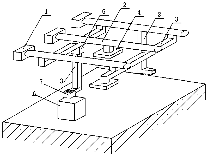
[0002] With the continuous development of electronic information technology, people pay more and more attention to the professional use environment of related electronic equipment. The construction of computer room has become a professional engineering field. For example, the construction of computer room site of Internet data center is the largest part of the initial investment of the project. , it is directly related to the stable operation and safety of the equipment, and the related requirements are complex and strict. The air supply and cooling system is an important sub-project of the construction of the computer room site. In the air-conditioning system of the air duct and the air outlet in the suspended ceiling, the cold air generated by the air conditioner enters the room through the air outlet. This device is simple and applicable for the general air-conditioning system in the computer room, and cannot fully meet the cooling needs of the computer room. The calorific value of the equipment is different, and it is distributed in different indoor space positions. The method of reducing the overall room temperature of the existing device cannot effectively cool down the equipment with a high calorific value or in an unfavorable position, and it is very easy to cause the operating temperature of such equipment to decrease. If it is too high, it will cause failure or shorten the life of the equipment. Therefore, the machine room adopts the method of lowering the position of the air outlet, but the construction is complicated, the maintenance is not easy, and the cooling effect is not obvious

Method used


Image

  • An air supply cooling device of computer room high-heating equipment

Examples


Embodiment Construction

[0010] The present invention will be further elaborated below in conjunction with the accompanying drawings.

[0011] Such as figure 1 As shown, the cooling device includes three air conditioners 1, an air duct network composed of three main air ducts 2 and multiple branch air ducts 3, and the main air ducts 2 are connected to the air conditioners 1 and extend to various indoor sections. One end of some branch air ducts 3 is directly connected to the main air duct 2, the other end is connected to the air outlet 4 integrated on the ceiling, and some branch air ducts 3 are connected to the three main air ducts 2 through connecting sleeves 5 If there is a connection, the connected main air duct 2 can be selected and controlled through the channel selection valve in the connecting sleeve, and the free end of the branch air duct 3 extends to the position facing the equipment 6 with a high calorific value or in an unfavorable position, and A fan 7 is installed at the port of the br...


PUM


Abstract

The invention discloses an air supply cooling device for high-heating equipment of a computer room. The device comprises an air conditioner (1), the air pipe comprises a main air pipe (2) and branch air pipes (3); the main air pipe (2) is communicated with the air conditioner (1); one end of each branch air pipe (3) is communicated with the main air pipe (2); according to the cooling device, on the basis of an existing cooling device, the air outlet is led out to the position near equipment, the main air pipe selection valve and the draught fan are additionally arranged in the branch air pipe,targeted matching of the single equipment is achieved, construction is easy, and the energy efficiency is high.

Description

technical field [0001] The invention relates to an air supply cooling device, in particular to a distributed cooling device for a machine room. Background technique [0002] With the continuous development of electronic information technology, people pay more and more attention to the professional use environment of related electronic equipment. The construction of computer room has become a professional engineering field. For example, the construction of computer room site of Internet data center is the largest part of the initial investment of the project. , it is directly related to the stable operation and safety of the equipment, and the related requirements are complex and strict. The air supply and cooling system is an important sub-project of the construction of the computer room site. In the air-conditioning system of the air duct and the air outlet in the suspended ceiling, the cold air generated by the air conditioner enters the room through the air outlet. This...

Claims


Application Information

Patent Timeline
IPC IPC(8): H05K7/20
Inventor 曾甫元
Owner DUJIANGYAN JINXIANG DECORATION ENG
Learn More