
Image instrument and imaging system thereof and control method of imaging system

An instrument and imaging technology, applied in the field of imaging equipment and its imaging system and imaging system control, can solve the problems of weak secondary fluorescent light, long exposure interval time, weak current, etc., achieve excellent portability, improve portability, The effect of easy operation

Pending Publication Date: 2019-05-10
深圳市纳诺艾医疗科技有限公司
View PDF11 Cites 1 Cited by
  • Summary
  • Abstract
  • Description
  • Claims
  • Application Information

AI Technical Summary

Problems solved by technology

However, this type of equipment cannot effectively solve the heat dissipation problem, and requires a long exposure interval. For example, every second of exposure, the heat dissipation is carried out at intervals of 60 seconds. It cannot be exposed for a long time, nor can it be continuously exposed. The application scenarios are still limited.
[0004] Another portable device using secondary fluorescence (XRF) is truly portable, but its current is weak, and the secondary fluorescence light is also very weak, so it can only be directly detected by the detection board at close range.
The application is also limited to the detection of sample components, without other more imaging purposes

Method used


Image

  • Image instrument and imaging system thereof and control method of imaging system
  • Image instrument and imaging system thereof and control method of imaging system
  • Image instrument and imaging system thereof and control method of imaging system

Examples


Embodiment 1

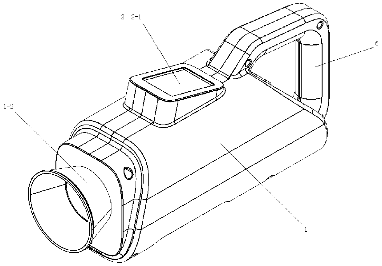
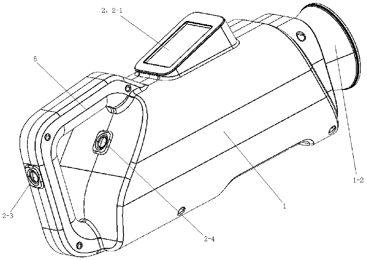
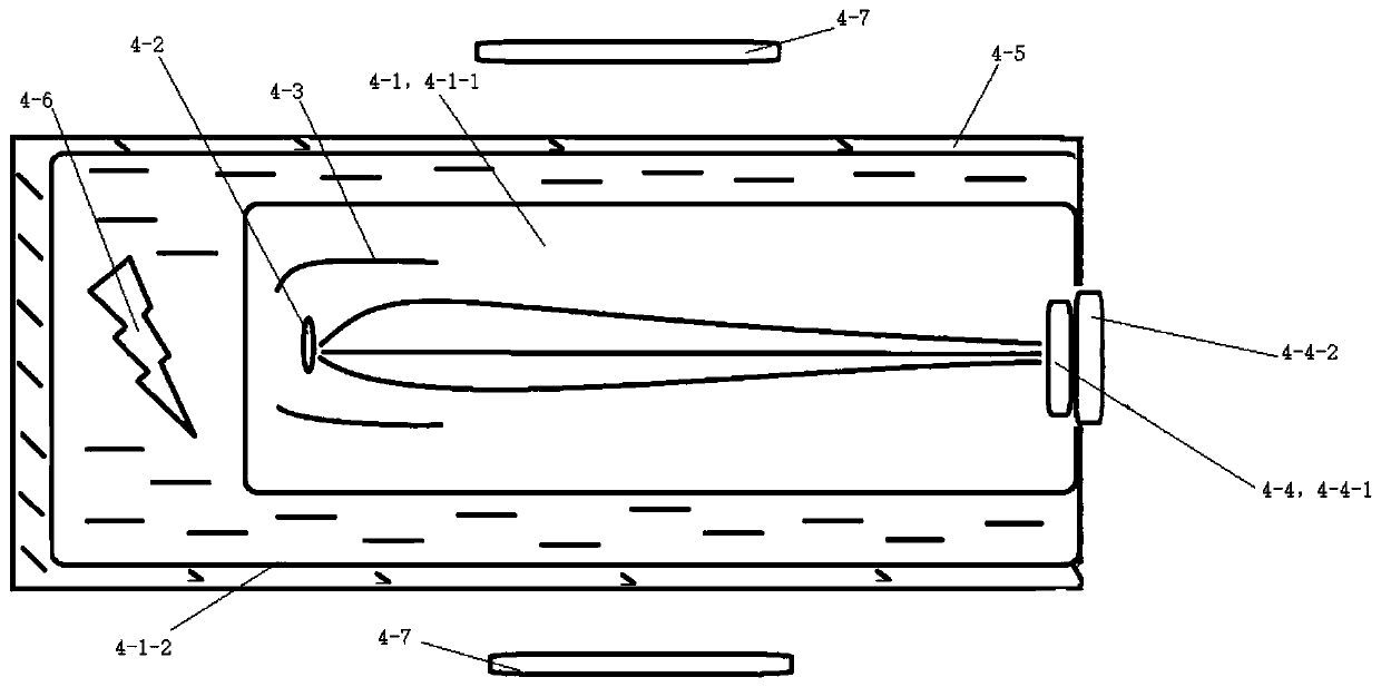
[0055] See Figure 1 to Figure 6 , the imaging device of this embodiment includes a casing 1 , a control module 2 , a low-voltage drive module 3 , a secondary fluorescent emission module 4 , a power supply module 5 and a handle 6 . The power supply module 5, the low-voltage driving module 3 and the secondary fluorescent emitting module 4 are electrically connected in sequence. The low-voltage driving module 3 and the secondary fluorescent emitting module 4 are both arranged in the casing 1 . The control module 2 is used to control the work of the secondary fluorescent emission module 4 . The secondary fluorescence emission module 4 is used to emit secondary fluorescence for exposure. The housing 1 is provided with a light outlet 1 - 1 aligned with the emitting end of the secondary fluorescent emitting module 4 . The handle 6 is arranged on the tail of the housing 1 , and the end of the tail of the housing 1 is inclined forward to provide more space for holding the handle 6 ...

Embodiment 2

[0085] See Figure 11 with Figure 12 , the imaging apparatus of this embodiment is basically the same as that of Embodiment 1, the difference is:

[0086] The housing 1 is in the shape of a square box, and the handle 6 is arranged on the top surface of the housing 1 . The central control panel 2-1 is detachably arranged on the casing 1, and is connected with the control circuit through wires or a remote transmitting module. The control circuit includes a processor and a remote receiving module. The remote transmitting module is a wireless transmitting module or a Bluetooth transmitting module, and the remote receiving module is a wireless receiving module or a Bluetooth receiving module. The housing 1 is provided with an interface connected with an external X-ray detection board. The casing 1 is provided with a hanging ring (not shown in the figure) for installing the shoulder strap. The imaging device of this embodiment can be carried on the shoulder or in a suitcase, a...

Embodiment 3

[0089] See Figure 13 with Figure 14 , the imaging device of this embodiment is basically the same as that of Embodiment 1, the difference is that: the housing 1 is rectangular, and the handle 6 is arranged at the bottom of the housing 1 . The central control panel 2 - 1 is arranged on the top surface of the housing 1 .


PUM


Abstract

The invention discloses an image instrument and an imaging system thereof and a control method of the imaging system. The image instrument comprises a casing, a control module, a low voltage driving module, a secondary fluorescent emitting module, a power module and a handle; the power module, the low voltage driving module and the secondary fluorescent emitting module are electrically connected in sequence; the low voltage driving module and the secondary fluorescent emitting module are both disposed in the casing; the control module is used for controlling the secondary fluorescent emittingmodule to operate; the secondary fluorescent emitting module is configured to emit secondary fluorescence for exposure; the casing is provided with an light exit port aligned with an emitting end of the secondary fluorescent emitting module; the handle is disposed at the casing. The instrument has excellent portable performance, and the secondary fluorescent emitting module capable of emitting thesecondary fluorescence greatly reduces the overall volume, and is suitable for mobile portable situations such as field work, emergency treatment, rescue application, home visit and the like.

Description

technical field [0001] The invention relates to an imaging device, its imaging system and a control method for the imaging system. Background technique [0002] The emission mechanism of the secondary fluorescence is different from that of the traditional Coolidge. Coolidge mainly uses Bremsstrahlung (bremsstrahlung) rays, while secondary fluorescence mainly uses characteristic spectral lines. Since the conversion efficiency of Bremsstrahlung is only 1 / 10,000, the equipment often requires high-power high-voltage power supply and heat dissipation, which is bulky and huge, and cannot be truly portable. Traditional portable devices are often traditional such as wheel shaft transmission, such as bedside machines, which can only provide limited power and light, or have limited functions or cannot achieve the ideal imaging effect of mainframes; at the same time, such devices still need external power supply, and mobile still needs Axle shifting devices or vehicle assistance are ...

Claims


Application Information

Patent Timeline
Patent Type & Authority Applications(China)
IPC IPC(8): A61B6/00
Inventor 程钊
Owner 深圳市纳诺艾医疗科技有限公司
Learn More