
Cutting device for machining

A cutting device and mechanical processing technology, applied in the direction of shearing devices, metal processing equipment, shearing machine accessories, etc., can solve the problems of angle adjustment that cannot be cut, cannot meet cutting requirements, pollute the working environment, etc., and achieve good work environment, enhance the scope of application, and improve work efficiency

Inactive Publication Date: 2019-05-10
淮北雷德机电科技有限公司
View PDF1 Cites 2 Cited by
  • Summary
  • Abstract
  • Description
  • Claims
  • Application Information

AI Technical Summary

Problems solved by technology

[0004] However, the above scheme still has the following limitations:
[0005] 1. The corresponding clamping is performed manually, and the corresponding efficiency is low; at the same time, only one piece can be cut at one time, and the corresponding efficiency is low;
[0006] 2. It is impossible to adjust the cutting angle accordingly, and cannot meet the specific cutting requirements; at the same time, a large amount of debris will be generated during the cutting process, polluting the working environment

Method used


Image

  • Cutting device for machining
  • Cutting device for machining
  • Cutting device for machining

Examples


Embodiment Construction

[0025] The following will clearly and completely describe the technical solutions in the embodiments of the present invention with reference to the accompanying drawings in the embodiments of the present invention. Obviously, the described embodiments are only some, not all, embodiments of the present invention. Based on the embodiments of the present invention, all other embodiments obtained by persons of ordinary skill in the art without making creative efforts belong to the protection scope of the present invention.

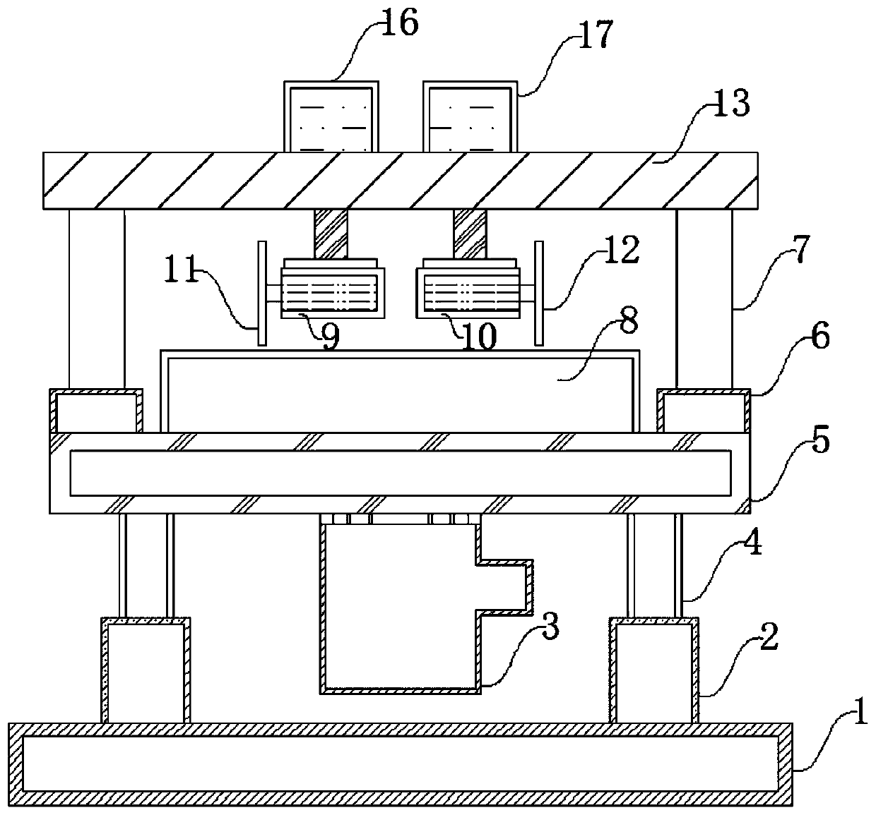
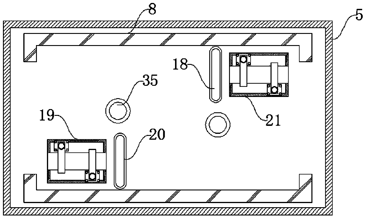
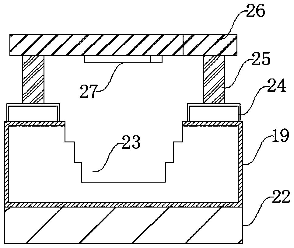
[0026] The present invention provides such Figure 1-7 The shown cutting device for machining includes a fixed seat 1 and a workbench 5, the upper end of the fixed seat 1 is welded with a sleeve 2, the inner side of the sleeve 2 is sleeved with a support column 4, and the support column 4 and the workbench 5 at the upper end are welded and fixed, and the left and right sides of the workbench 5 are welded with a fixed base 6, and the upper end of the fixed base...


PUM


Abstract

The invention discloses a cutting device for machining. The device comprises a fixing base and workbench, wherein sleeves are welded at the upper end of the fixing base, supporting columns are connected to the inner sides of the sleeves in a sleeve mode, the supporting columns are fixedly welded on the workbench at the upper end, fixing seats are welded to the left side and the right side of the workbench, fixing columns are welded at the upper ends of the fixing seats, and a mounting frame is welded at the upper ends of the fixing columns. According to the device, the step-shaped design of afixing groove can be applied to objects with different widths, so that the corresponding application range is enhanced, meanwhile, a butt joint hole and a sliding hole are designed on a fixing plate,a first fixing hole and a second fixing hole arranged in the bottom side of a first supporting table and in the bottom side of a second supporting table respectively are matched, so that the corresponding angle adjustment can be carried out on the first supporting table and the second supporting table, the corresponding inclined cutting can be carried out according to the corresponding requirements, the corresponding machining requirements are met, the flexible and convenient effects are achieved, the structural design is compact and reasonable, the strong practicability is achieved, and the device is suitable for popularization.

Description

technical field [0001] The invention belongs to the field of machinery, and in particular relates to a cutting device for machining. Background technique [0002] In the field of mechanical processing and production, it often involves the processing and application of mechanical parts. The purpose of processing the cross-section of mechanical parts is mainly to obtain a cross-section that matches with other parts of the machine. The basic requirement for the cut cross-section is to require its surface to be flat and to avoid uneven surface. At present, the cutting of the cross-section of mechanical parts is generally done by blade cutting. For relatively hard processed parts, the cutting knife may be relatively inclined during the cutting process, resulting in unevenness in the cut cross-section. Problems with unevenness and sloping cuts. [0003] To this end, CN205704377U discloses a cutting device for mechanical processing, including a processing table, the processing ta...

Claims


Application Information

Patent Timeline
Patent Type & Authority Applications(China)
IPC IPC(8): B23D19/00B23D33/00B23D33/02B23Q11/00
Inventor 吴新明李洋
Owner 淮北雷德机电科技有限公司
Learn More