Plastic bag strapping machine
A technology of plastic bags and strapping machines, which is applied to the parts of strapping machines, strapping materials, etc., can solve the problems of not being able to be tightened, rubber bands that are easy to shake, and easy to break, so as to reduce the probability of machine work errors, structure and work The program is simple and stable, and the structure is compact and simple
- Summary
- Abstract
- Description
- Claims
- Application Information
AI Technical Summary
Problems solved by technology
Method used
Image
Examples
Embodiment 2
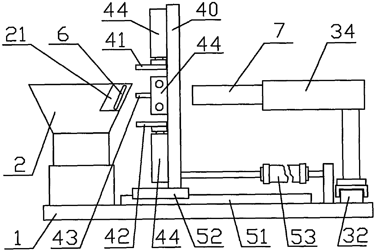
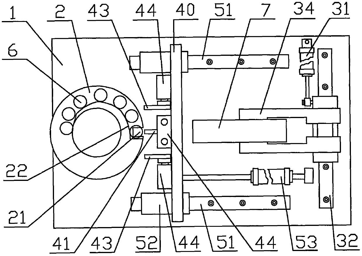
[0048] Embodiment two, such as Figure 12 As shown: the main difference between the second embodiment and the first embodiment is: one is that one side of the bracket 40 is hinged on the frame 1, and the insertion movement mechanism is a swing cylinder 55; Mechanism 9 is installed on the plastic bag conveying device 3, and rib removal mechanism 9 is a kind of rib removal bar 91, and rib removal bar 91 is installed on the both sides of mechanical clamp 34, and two side positions of each side are respectively installed two rib removal bars. The rib bar 91 makes the space enclosed by the 4 rib bars 91 larger than the width of the struts 43 on both sides after being stretched; a hinged column 54 is installed on one side of the support 40 so that the support 40 passes through the hinged column 54 is hinged on the frame 1, and a swing cylinder 55 is installed on the hinge column 54 and the bracket of the frame 1, the vibration plate device 2 is installed on the front right side of t...
Embodiment 3
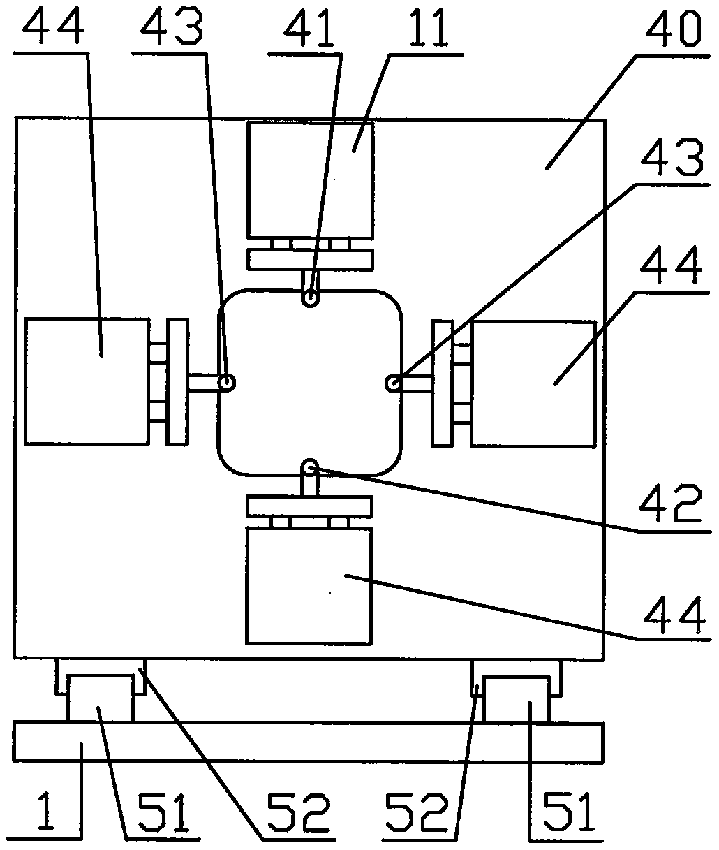
[0050] Embodiment three, the main difference of embodiment three is: as Figure 14 As shown, the U-shaped notch 21 is arranged obliquely; the bottom side support bar 42 is fixedly arranged on the bottom side of the bracket 40, corresponding to the bottom of the U-shaped notch 21; Side strut 41; a two-side strut 43 is installed at a position corresponding to the upper side strut 41 directly below, so that the two-side strut 43 corresponds to the bottom side strut 42 left and right, and also corresponds to the upper side strut 41 Corresponding up and down, so that a right-angled triangle is formed between the two side struts 43, the bottom side struts 42, and the upper side struts 41; The upper position of the upper side, and corresponding to the upper side strut 41 left and right, the two side struts 43, the upper side strut 41 are respectively connected with the strut cylinder 44, and the strut cylinder 44 is installed on the support 40 respectively.
[0051] The working step...
Embodiment 4
[0052] Embodiment four, the difference of embodiment four mainly lies in: Figure 19 , Figure 20 As shown, the rubber band stretching device 4 is installed on the lifting mechanism, and the lifting mechanism includes a guide rod cylinder 8, the rubber band stretching device 4 is connected on the cylinder rod seat of the guide rod cylinder, and the cylinder body of the guide rod cylinder is connected On the slide block 53; what drives the support 40 to move back and forth is a kind of common cylinder 56; the slide block 33 on the guide rail 32 of the plastic bag transfer device 3 is provided with a bracket 35, and two mechanical clips 34 are arranged on the bracket up and down 35, the muscle-removing mechanism 9 is arranged on the plastic bag conveying device 3, and the muscle-removing mechanism is a kind of advancing baffle plate 92; the both sides front end positions of the mechanical clamp 34 are also respectively provided with the baffle plate 92 for removing the muscle. ...
PUM
 Abstract
Description
Claims
Application Information
 - R&D
- Intellectual Property
- Life Sciences
- Materials
- Tech Scout
- Unparalleled Data Quality
- Higher Quality Content
- 60% Fewer Hallucinations
Browse by: Latest US Patents, China's latest patents, Technical Efficacy Thesaurus, Application Domain, Technology Topic, Popular Technical Reports.
© 2025 PatSnap. All rights reserved.Legal|Privacy policy|Modern Slavery Act Transparency Statement|Sitemap|About US| Contact US: help@patsnap.com


