
Milling wheel for underground continuous wall excavation and two-wheel slot milling machine

A milling wheel and tooth milling technology, which is applied in the field of milling wheels and double-wheel slot milling machines, can solve the problems of difficult rock breaking, increased construction costs, and low construction efficiency, so as to maintain stable milling wheel construction, reduce milling gear loss, The effect of improving rock breaking ability

Pending Publication Date: 2019-05-10
JIANGSU XCMG CONSTR MASCH RES INST LTD +1
View PDF0 Cites 0 Cited by
  • Summary
  • Abstract
  • Description
  • Claims
  • Application Information

AI Technical Summary

Problems solved by technology

[0003] However, during the excavation of strata above medium-hard rock, it is difficult to break the rock, and there are problems such as low construction efficiency and large wear of the milling teeth.
Affect the construction progress of the underground diaphragm wall project and increase the construction cost
[0004] The prior art has the following disadvantages: in the prior art, the milling wheel makes the cutting wheel in a vibrating state during the construction project through the eccentric structure of the working tool ring path and the axis of rotation of the drive shaft to improve the construction efficiency. Due to the vibration of the cutting wheel, the drive The shaft and the whole machine are always in a vibrating state, which will aggravate the damage of the parts of the whole machine and reduce the reliability and service life of the cutting wheel and the whole machine

Method used


Image

  • Milling wheel for underground continuous wall excavation and two-wheel slot milling machine
  • Milling wheel for underground continuous wall excavation and two-wheel slot milling machine
  • Milling wheel for underground continuous wall excavation and two-wheel slot milling machine

Examples


Embodiment Construction

[0031] The following will clearly and completely describe the technical solutions in the embodiments of the present invention with reference to the accompanying drawings in the embodiments of the present invention. Obviously, the described embodiments are only some, not all, embodiments of the present invention. The following description of at least one exemplary embodiment is merely illustrative in nature and in no way taken as limiting the invention, its application or uses. Based on the embodiments of the present invention, all other embodiments obtained by persons of ordinary skill in the art without creative efforts fall within the protection scope of the present invention.

[0032] The relative arrangements of components and steps, numerical expressions and numerical values ​​set forth in these embodiments do not limit the scope of the present invention unless specifically stated otherwise. At the same time, it should be understood that, for the convenience of descriptio...


PUM


Abstract

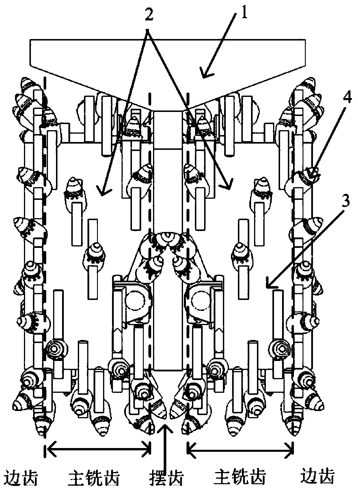
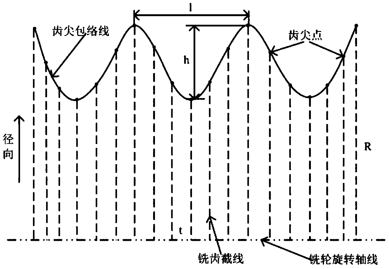
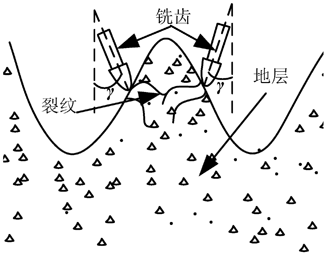
The invention discloses a milling wheel for underground continuous wall excavation and a two-wheel slot milling machine. In a main milling tooth region, milling teeth are evenly arranged in the axis direction of a roller, and the tooth tip circle radius of the milling teeth are periodically fluctuated in the axis direction of the roller, so that the bottom of corresponding milling groove forms anuneven milling section with periodic fluctuations; and in the circumferential direction of the roller, a plurality of milling teeth are cut into a rock in a skipped mode, so that all the milling teethare located in the axial direction, the diameter direction and the circumferential direction, so that all the milling teeth create milling free surfaces in the three dimensions mutually, each millingtooth can conduct unilateral crushing or bilateral crushing when milling a rock formation, cracks are easily crossed mutually, the milling resistance of each milling tooth is reduced, thus, the rockbreaking ability of the milling wheel is improved, the losses of the milling teeth are reduced, and the construction efficiency of the two-wheel slot milling machine is improved.

Description

technical field [0001] The invention belongs to the technical field of underground diaphragm wall excavation, and relates to a milling wheel and a double-wheel groove milling machine used for excavating an underground diaphragm wall. Background technique [0002] Double-wheel slot milling machine is the core equipment for the construction of underground diaphragm wall, which has the characteristics of large slot depth, high verticality and strong stratum adaptability. The milling wheel is responsible for the milling and crushing of rock and soil strata. It is the core working device of the double-wheel slot milling machine and plays a key role in the construction efficiency of the whole machine. [0003] However, during the excavation of strata above medium-hard rock, it is difficult to break the rock, and there are problems such as low construction efficiency and large wear of the milling teeth. It affects the construction progress of the underground diaphragm wall project...

Claims


Application Information

Patent Timeline
IPC IPC(8): E02F5/08E02F5/14
CPCY02P70/10
Inventor 康凯旋何冰贾海波张继光
Owner JIANGSU XCMG CONSTR MASCH RES INST LTD
Learn More