Drilling bit spiral impact device

A technology of impact device and drill bit, which is applied to driving devices for drilling in wellbore, drilling equipment, earth-moving drilling, etc. , increase the effect of the rock crushing effect

Inactive Publication Date: 2015-08-26
CHINA UNIV OF GEOSCIENCES (WUHAN)
View PDF11 Cites 6 Cited by
  • Summary
  • Abstract
  • Description
  • Claims
  • Application Information

AI Technical Summary

Problems solved by technology

However, practice shows that as the well depth increases, the pressure loss of the drilling circulation medium increases. When the well depth is very large, the circulation medium may only meet the requirements of circulating rock carrying, and the working status of the above-mentioned devices will be greatly affected. It may not work normally or even affect the drilling operation; when the drilling circulation medium is air or aerated drilling fluid and other media with a large compressibility coefficient, the above devices are difficult to work normally

Method used


Image

  • Drilling bit spiral impact device
  • Drilling bit spiral impact device
  • Drilling bit spiral impact device

Examples


Embodiment 1

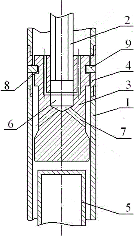
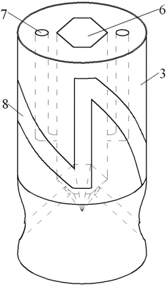
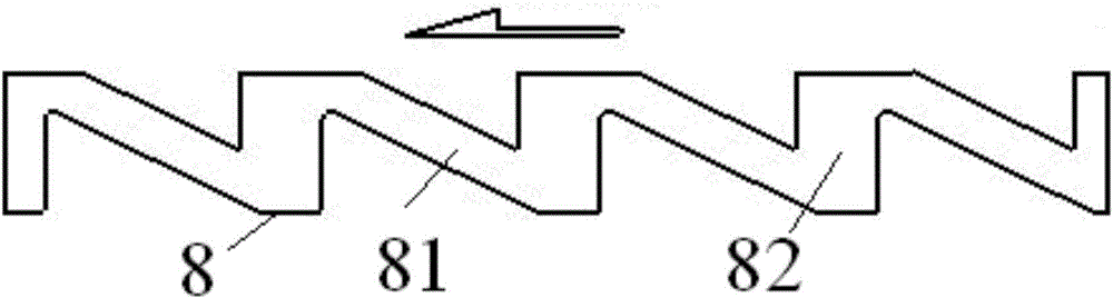
[0021] Embodiment 1: a kind of drill bit spiral impact device, such as figure 1 and figure 2 As shown, it includes an outer casing 1, an impact hammer 3 installed in the outer casing in the vertical direction and a lower joint 5 connected to the drill bit. The outer casing includes an upper casing and a lower casing positioned below the upper casing. The bushing and the lower bushing are connected through a guide sleeve 4 located between them, and the two ends of the guide bush are respectively threaded with the upper bushing and the lower bushing, and the center of the impact hammer is provided with a power input shaft that drives the impact hammer to rotate 2. The center of the impact hammer is provided with a blind hole 6 with the same cross-sectional shape as the lower end of the power input shaft and a drain hole 7 connected to the blind hole. The liquid outlet of the drain hole is located on the outer surface of the impact hammer, and the power input The lower end of t...

Embodiment 2

[0023] Embodiment 2: a kind of drill bit spiral impact device, such as Figure 4 As shown, it includes an outer casing 1, an impact hammer 3 installed in the outer casing in the vertical direction and a lower joint 5 connected to the drill bit. The outer casing includes an upper casing and a lower casing positioned below the upper casing. The bushing and the lower bushing are connected through a guide sleeve 4 located between them, and the two ends of the guide bush are respectively threaded with the upper bushing and the lower bushing, and the center of the impact hammer is provided with a power input shaft that drives the impact hammer to rotate 2. The center of the impact hammer is provided with a blind hole 6 with the same cross-sectional shape as the lower end of the power input shaft and a drain hole 7 connected to the blind hole. The liquid outlet of the drain hole is located on the outer surface of the impact hammer, and the power input The shaft is connected with the ...


PUM


Abstract

The invention provides a drilling bit spiral impact device which comprises an outer casing pipe, an impact hammer and a lower connector which are mounted in the outer casing pipe in sequence in the vertical direction; a power input shaft is arranged at the center of the impact hammer; the power input shaft is movably connected with the impact hammer and drives the impact hammer to rotate; the impact hammer is connected with the outer casing pipe through a guide mechanism; the impact hammer moves up and down along the power input shaft under the action of the guide mechanism; the guide mechanism comprises a saw-toothed ring groove which is formed by spiral line grooves and vertical grooves which are alternatively formed and two or more guide blocks positioned in the saw-toothed ring groove; the spiral line grooves and the vertical grooves are identical in number and are mutually communicated; the guide blocks are uniformly distributed on the inner wall of the outer casing pipe and the saw-toothed ring groove is formed in the side surface of the impact hammer. The drilling bit spiral impact device does not need quick-wear parts like springs, is simple in structure, convenient to maintain, low in cost, suitable for coring of hole sections of various depths and not influenced by hole depth and pressure change of a water column, and can improve the rock breaking effect and improve the roundtrip meterage length.

Description

technical field [0001] The invention relates to an impact device, in particular to a spiral impact device for well drilling, which belongs to the field of core drilling. Background technique [0002] Deep core drilling often encounters a variety of complex formations, especially when encountering hard formations. The conventional rotary method is used to drive the drill bit to rotate and break rocks, resulting in poor drilling efficiency and short return footage, which affects the construction progress and increases production cost. [0003] In order to solve the above problems, a percussion rotary drilling technology has emerged in drilling engineering, that is, in the conventional rotary drilling process, without adding other ground equipment, the diameter of the drill collar is roughly equivalent to the diameter of the drill collar on the upper side of the drill bit and the lower side of the drill collar. During the drilling process, the impactor that follows the rotatio...

Claims


Application Information

Patent Timeline
Patent Type & Authority Applications(China)
IPC IPC(8): E21B4/16
CPCE21B4/16
Inventor 张惠张晓西胡郁乐
Owner CHINA UNIV OF GEOSCIENCES (WUHAN)
Why Eureka
Try Eureka