
Stiff structure beam-column joint and construction method

A technology of beam-column joints and construction methods, which is applied in the direction of building structure and construction, can solve the problem that the construction quality of the core area of ​​beam-column joints is difficult to obtain due guarantee, the welding operation surface of the steel bars at the bottom of the beam is insufficient, and the welding quality of the ribbed plates is solved. Difficult to control and other problems, to achieve the effect of improving the quality of positioning welding, reducing the difficulty of stirrup construction, and improving the construction process

Active Publication Date: 2021-06-18
中峥建设集团有限公司
View PDF0 Cites 0 Cited by
  • Summary
  • Abstract
  • Description
  • Claims
  • Application Information

AI Technical Summary

Problems solved by technology

[0004] The emergence of steel concrete and prestress plays a prominent role in realizing "large-span space" for building structures. However, when steel beams, steel columns, prestress, and even multi-beam intersections appear at the same time, the construction process is complicated and the construction is difficult. In particular, the construction quality of the core area of ​​such complex beam-column joints is difficult to get due guarantee
The beam-column core area of ​​such complex joints often has dense and intricately arranged steel bars, difficult to meet the anchorage length of the steel bars, difficult to control the welding quality with the rib plate, insufficient welding operation surface for the steel bars at the bottom of the beam, and difficult to control the opening ratio of the steel members. The superimposed arrangement of steel bars leads to construction problems such as super-high slabs

Method used


Image

  • Stiff structure beam-column joint and construction method
  • Stiff structure beam-column joint and construction method
  • Stiff structure beam-column joint and construction method

Examples


Embodiment Construction

[0026] The following will clearly and completely describe the technical solutions in the embodiments of the present invention with reference to the accompanying drawings in the embodiments of the present invention. Obviously, the described embodiments are only some, not all, embodiments of the present invention. All other embodiments obtained by persons of ordinary skill in the art based on the embodiments of the present invention belong to the protection scope of the present invention.

[0027] Those skilled in the art should understand that in the disclosure of the present invention, the terms "vertical", "transverse", "upper", "lower", "front", "rear", "left", "right", " The orientation or positional relationship indicated by "vertical", "horizontal", "top", "bottom", "inner", "outer", etc. is based on the orientation or positional relationship shown in the drawings, which are only for the convenience of describing the present invention and The above terms should not be con...


PUM


Abstract

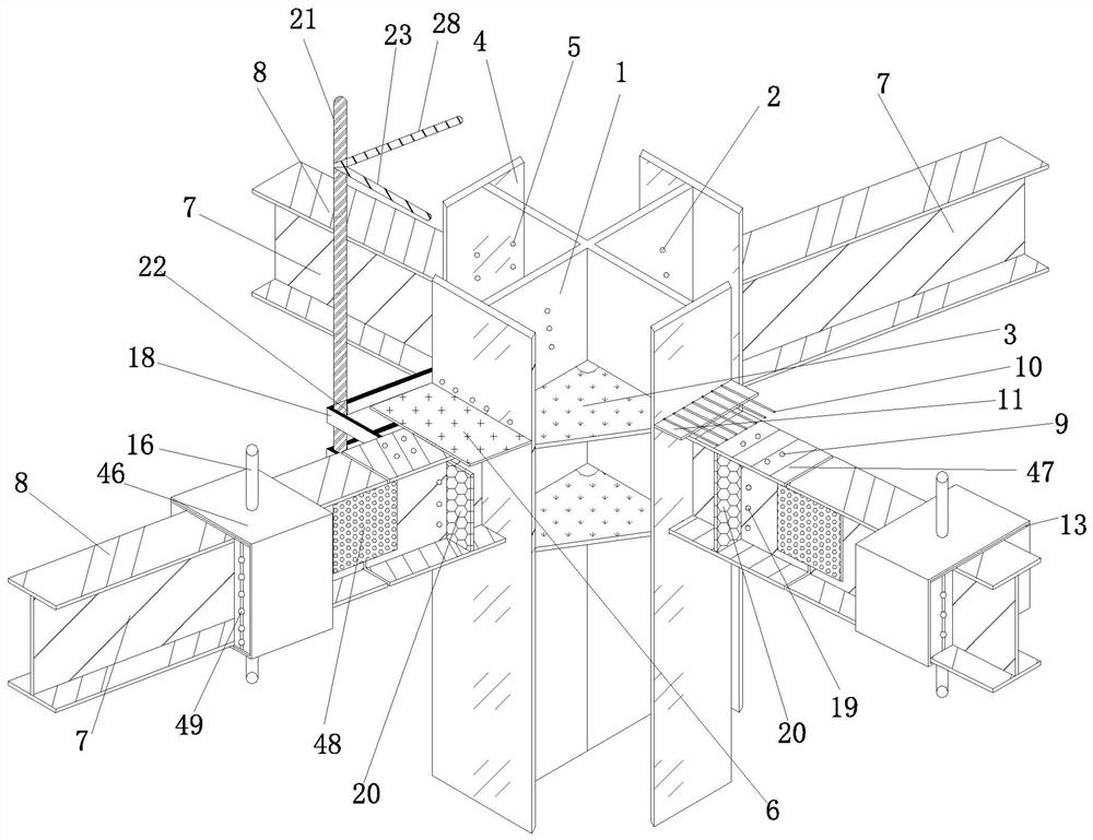
The invention discloses a beam-column joint of a rigid structure and a construction method thereof, which mainly include (8) processing and manufacturing of an integral ring-belt steel plate; Fabrication of stirrup frame tube; (11) Binding column stirrup cage; (12) Installing steel beam reinforcement; (13) Binding and welding of beam-column reinforcement in the joint area; (14) Setting up the formwork system in the joint core area; (15) (16) Column, beam and slab formwork installation; (17) Steps such as concrete pouring in the joint area, adopting the joint structure of the beam-column joint section steel and the steel bar of the rigid structure, and the integral stirrup frame tube is shaped and bound to the tire frame At the same time, the stirrups in the beam-column joint area are replaced by the strength of the ring-belt steel plate, and the integral formwork support system on the upper part of the falling frame solves the problem of formwork support in the core area of ​​​​the beam-column joint, and at the same time greatly speeds up the construction speed. In addition, the formwork can be Realize recycling and save costs.

Description

technical field [0001] The invention relates to the field of civil engineering, in particular to a beam-column joint of a stiff structure and a construction method, and is particularly suitable for the construction of a beam-column joint of a stiff structure. Background technique [0002] In response to the continuous emergence of various new structural forms in the field of architecture in our country, the methods of structural design have gradually become diversified. From the design point of view, it is necessary to ensure the "safety and firmness" of the physical structure while also ensuring the "functional use, beautiful and exquisite" of the formed building. Undoubtedly, with the continuous development of my country's construction industry, large-scale commercial complex projects Expectations for the latter are also constantly increasing, that is to say, on the premise of meeting the "limit state of bearing capacity", users have a deeper understanding and requirements ...

Claims


Application Information

Patent Timeline
Patent Type & Authority Patents(China)
IPC IPC(8): E04B1/58
Inventor 王新泉
Owner 中峥建设集团有限公司
Learn More