
Dynamic sealing device for turbo pump and turbo pump set

A technology for dynamic sealing and turbo pumps, which is applied in the sealing field of turbo pumps. It can solve the problems of poor rigidity and stability of turbo pumps, low critical speed of turbo pump shafts, and complex structures, and achieve compact overall layout, shortened axial dimensions, and reduced The effect of consumption

Active Publication Date: 2019-05-10
SHAANXI LANDSPACE TECH CO LTD
View PDF7 Cites 15 Cited by
  • Summary
  • Abstract
  • Description
  • Claims
  • Application Information

AI Technical Summary

Problems solved by technology

The multi-stage seal structure will result in a large axial space size and complex structure of the seal structure, resulting in a low critical speed of the turbine pump shaft and poor rigidity and stability of the turbine pump
[0006] 2) The inert gas isolation is usually introduced by the floating ring, resulting in a large consumption of blow-off gas when the liquid engine is working

Method used


Image

  • Dynamic sealing device for turbo pump and turbo pump set
  • Dynamic sealing device for turbo pump and turbo pump set
  • Dynamic sealing device for turbo pump and turbo pump set

Examples


Embodiment Construction

[0028] Various exemplary embodiments of the present invention will now be described in detail. The detailed description should not be considered as a limitation of the present invention, but rather as a more detailed description of certain aspects, features and embodiments of the present invention.

[0029] It will be apparent to those skilled in the art that various modifications and changes can be made in the specific embodiments of the present invention described herein without departing from the scope or spirit of the present invention. Other embodiments will be apparent to the skilled person from the description of the present invention. The specification and examples in this application are exemplary only.

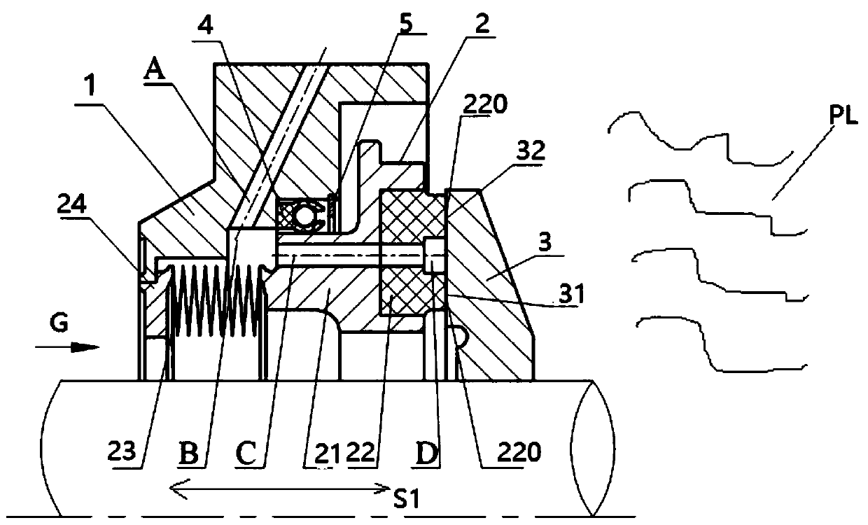
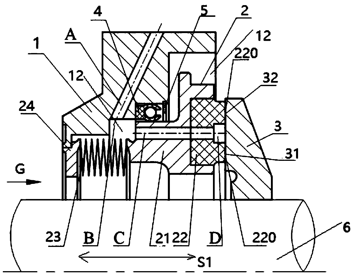
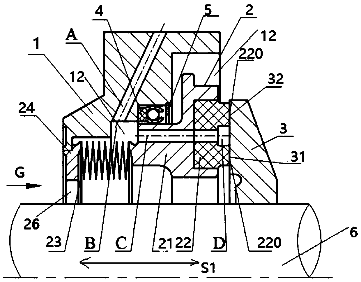
[0030] For example, the oxidant pump and the fuel pump in the turbopump group of the liquid engine can be arranged coaxially, and the dynamic sealing device can be arranged between the oxidizer pump and the fuel pump, so as to prevent the leaked oxidant and fuel from...


PUM


Abstract

The invention provides a dynamic sealing device for a turbo pump and a turbo pump set. The dynamic sealing device comprises a shell, a static ring assembly and a moving ring, wherein the static ring assembly is arranged in the shell, the end, in the first direction, of the static ring assembly is connected with the shell, the other end of the static ring assembly is used for abutting against the moving ring, the inner side of the shell and the static ring assembly define a discharge cavity, one end of the shell communicates with the discharge cavity, the other end of the shell is provided witha discharge channel communicating with the external environment, a groove is formed in the other end of the static ring assembly, the moving ring seals the groove by abutting against a sealing end surface of the other end, the static ring assembly comprises a drainage hole in the first direction, one end of the drainage hole communicates with the groove, and the other end of the drainage hole communicates with the discharge cavity. According to the dynamic sealing device, the structure of the turbo pump set can be simplified, the size of the axial direction of the turbo pump set is shortened,so that the performance of the turbo pump set is improved.

Description

technical field [0001] The invention relates to the technical field of turbo pump sealing, in particular to a dynamic sealing device for a turbo pump and a turbo pump set. Background technique [0002] As an important part of the pump-pressed liquid rocket engine, the turbo pump is used to provide the oxidant and fuel required for the engine to work. In order to prevent propellant leakage, oxidant pumps and fuel pumps usually need to be equipped with effective dynamic sealing devices. [0003] The performance of the dynamic sealing device will directly determine the life and reliability of the turbo pump, which is one of the key technologies of the liquid rocket engine. Especially for liquid oxygen, liquid hydrogen or methane and other low-temperature easy-to-vaporize media, it is usually necessary to set up two or more seals to form a combined seal. For example, in an existing turbopump using a multi-stage combined sealing method, the first few stages of the multi-stage c...

Claims


Application Information

Patent Timeline
IPC IPC(8): F04D29/12F02K9/46
Inventor 张树强刘磊王磊赵玉龙杨军崔生磊张力豪陈展韦华裴曦
Owner SHAANXI LANDSPACE TECH CO LTD
Learn More