
Photovoltaic module for polar environment

A photovoltaic module and environmental technology, applied in photovoltaic power generation, photovoltaic modules, electrical components, etc., can solve problems such as inconsistent thermal expansion coefficient, low power generation efficiency, and affecting power generation of photovoltaic modules, and achieve low glass transition temperature and embrittlement temperature, Reasonable working method and simple overall structure

Active Publication Date: 2019-05-10
48TH RES INST OF CHINA ELECTRONICS TECH GROUP CORP
View PDF5 Cites 0 Cited by
  • Summary
  • Abstract
  • Description
  • Claims
  • Application Information

AI Technical Summary

Problems solved by technology

The embrittled encapsulation material loses its protective effect on the solar cells, and the photovoltaic modules are very easy to be damaged, resulting in the failure of the photovoltaic modules to generate electricity normally
In addition, the thermal expansion coefficients of various constituent materials of photovoltaic modules are inconsistent, which may easily lead to mismatching in the low temperature environment of the polar region
In particular, the thermal expansion coefficients of photovoltaic ribbons and solar cells differ greatly, and the deformation of the ribbons in the low-temperature environment of the extreme region will lead to shrinkage and fracture of the ribbons or damage to adjacent solar cells.
[0004] In addition, because the blizzard in the polar region will accumulate snow on the photovoltaic module, it will also affect the light transmission performance of the photovoltaic module; and the temperature in the polar region is low, and the snow will not melt on the surface of the photovoltaic module. If the snow is not removed, it will grow Time affects the power generation of photovoltaic modules, resulting in low power generation efficiency
In addition, too much snow on the surface of photovoltaic modules will also increase the weight of photovoltaic modules, and there is a risk of crushing photovoltaic modules

Method used


Image

  • Photovoltaic module for polar environment
  • Photovoltaic module for polar environment
  • Photovoltaic module for polar environment

Examples


Embodiment Construction

[0026] The present invention will be further described below in conjunction with the accompanying drawings and specific embodiments.

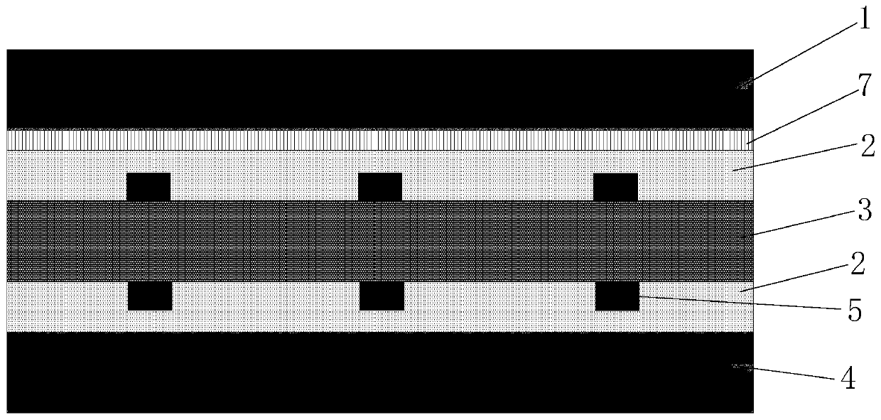
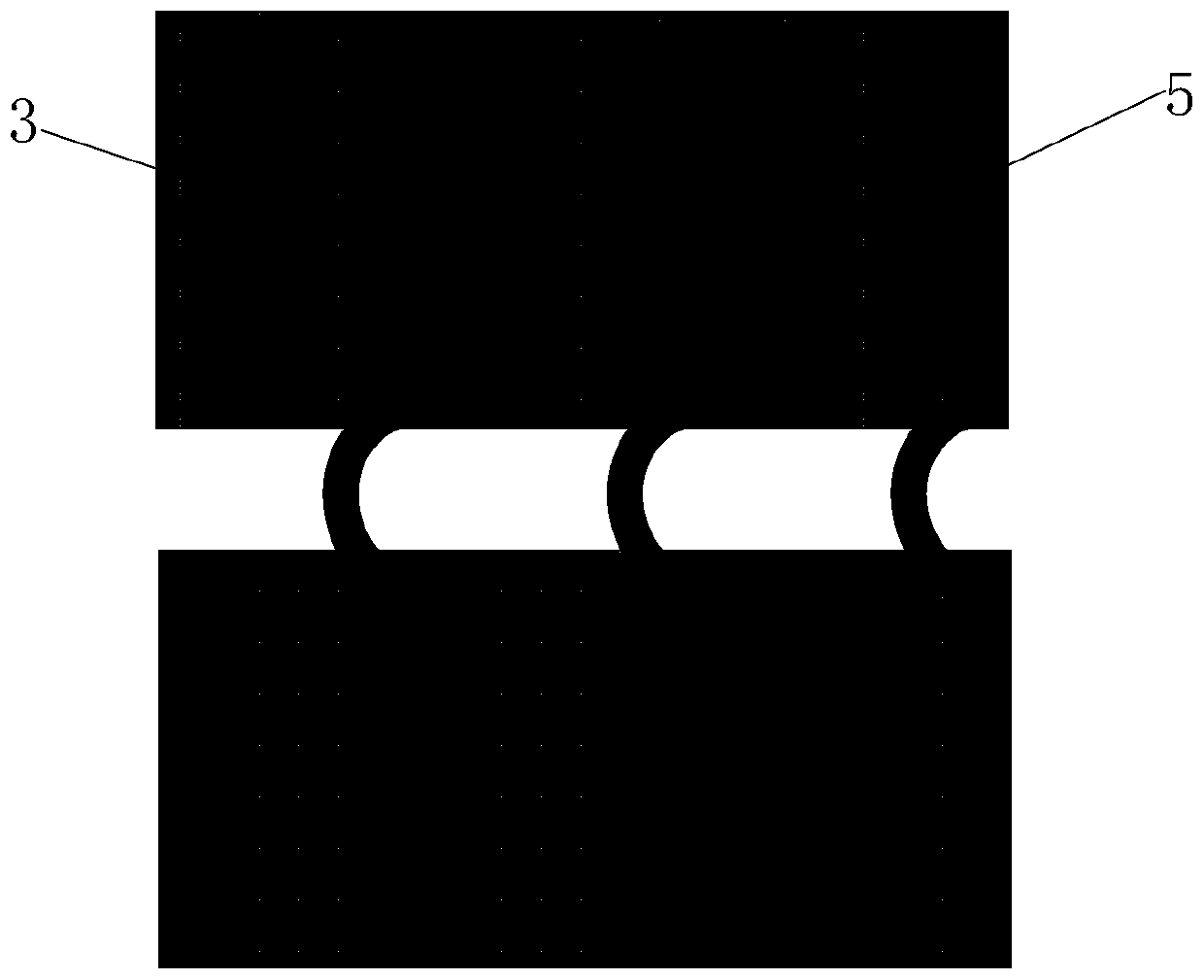
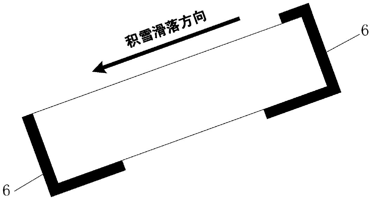
[0027] Such as Figure 1 to Figure 3 As shown, the photovoltaic module used in the polar region environment of this embodiment includes a double-sided power generation solar cell 3 that is encapsulated and protected by an encapsulant 2 on both sides. Both sides of the cell 3 can generate electricity, and both sides of the cell 3 The front glass layer 1 and the rear glass layer 4 are respectively provided to protect both sides of the battery sheet 3; the inside of the front glass layer 1 is provided with a heating module 7 for heating the front glass layer 1; the heating module 7 and the photovoltaic module The controller is connected; when the controller detects that the power generation of the front side of the battery sheet 3 is lower than that of the back side, it can judge that there is snow on the front glass layer 1. At this time, the hea...


PUM

PropertyMeasurementUnit
Diameteraaaaaaaaaa

Abstract

The invention discloses a photovoltaic module for polar environment. The photovoltaic module for polar environment comprises a double-sided power generation solar battery piece, the two sides of the double-sided power generation solar battery piece are subjected to packaging protection through a packaging adhesive, and a front glass layer and a rear glass layer are separately disposed on the two sides of the battery piece; a heating module for heating the front glass layer is arranged on the inner side of the front glass layer; the heating module is connected with a controller of the photovoltaic module; and when the controller detects that the generated energy of the front side of the battery piece is less power than that of the reverse side of the battery piece, the heating module is started, and otherwise, the heating module is turned off. The photovoltaic module for the polar environment has the advantages of simple structure, resistance to snow accumulation, high power generationefficiency, safety and reliability and the like.

Description

technical field [0001] The invention mainly relates to the technical field of photovoltaics, in particular to a photovoltaic module used in polar environment. Background technique [0002] At present, photovoltaic solar cell modules (referred to as photovoltaic modules) are divided into space-use photovoltaic modules and ground-use photovoltaic modules according to application scenarios. Since space photovoltaic modules are mainly used on satellites, the application environment and requirements are completely different from those on the ground. The type and structure of photovoltaic modules are different from those used on the ground, and space photovoltaic modules are expensive. At present, the minimum temperature test of ground photovoltaic modules is generally designed at -40°C, which can meet most of the application environments on the ground. However, the lowest temperature in polar regions such as the Antarctic and the Arctic is below -50°C, and it is difficult for gr...

Claims


Application Information

Patent Timeline
IPC IPC(8): H01L31/048H02S40/12
CPCY02E10/50
Inventor 唐荣黄齐鸣周洪彪蒋超
Owner 48TH RES INST OF CHINA ELECTRONICS TECH GROUP CORP
Learn More