
MIMO antenna system

An antenna system and antenna technology, applied in antennas, antenna coupling, antenna arrays, etc., can solve the problems that metal frames are difficult to achieve good performance and isolation of multiple antenna structures, and achieve aesthetic appearance, structural strength, and good reliability Effect

Inactive Publication Date: 2019-05-10
AAC TECH NANJING
View PDF5 Cites 2 Cited by
  • Summary
  • Abstract
  • Description
  • Claims
  • Application Information

AI Technical Summary

Problems solved by technology

With the development of the fifth-generation mobile communication system 5G, it is necessary to deploy 5G in two C-Band frequency bands, and it is necessary to use 4*4 or even 8*8 MIMO antenna design. In the existing antenna system, the metal frame is limited. The number of cracks and the limited space make it difficult to achieve the relevant requirements for good performance and isolation after the layout of multiple antenna structures

Method used


Image

  • MIMO antenna system
  • MIMO antenna system
  • MIMO antenna system

Examples


Embodiment Construction

[0020] The present invention will be further described below in conjunction with the accompanying drawings and embodiments.

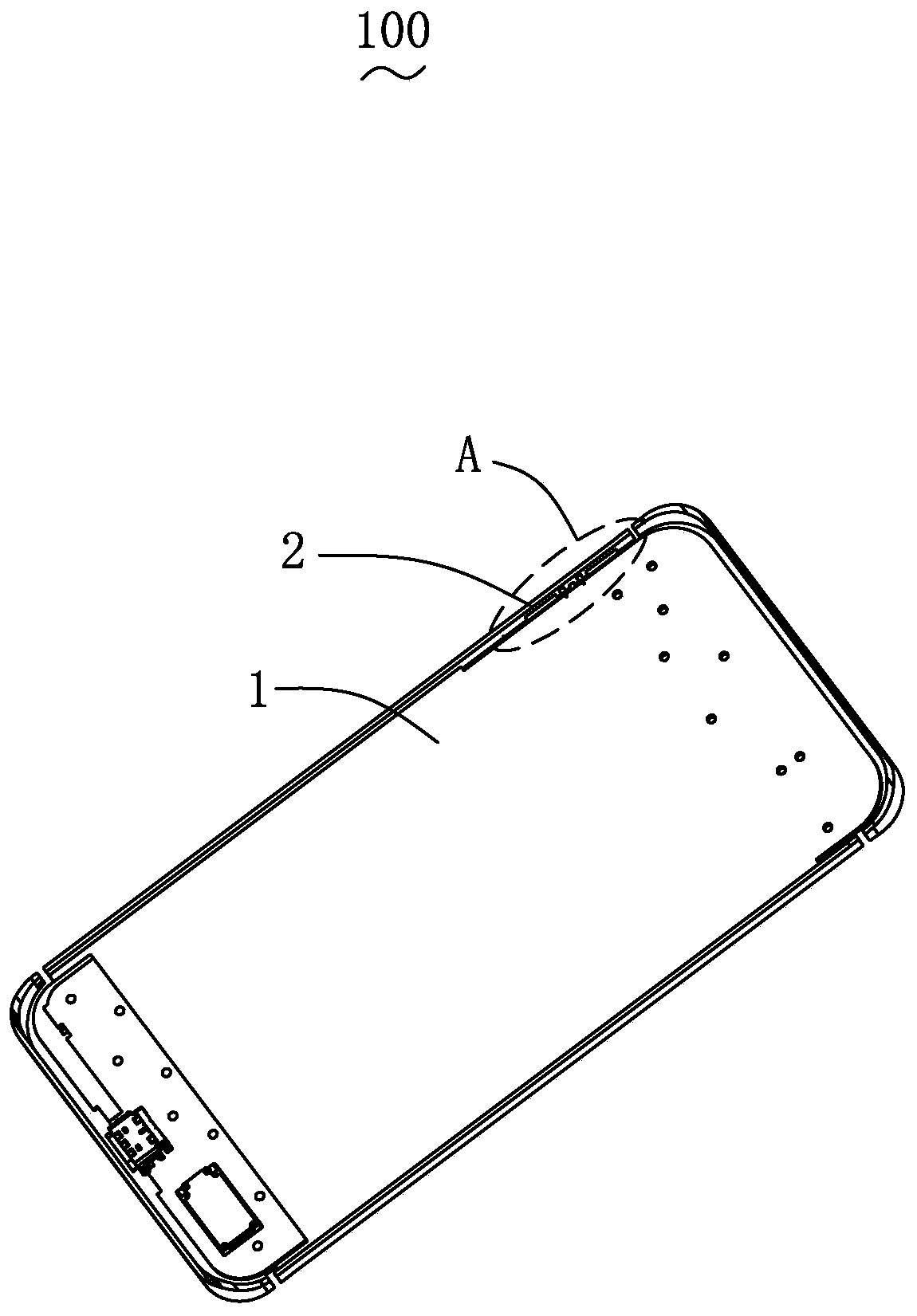
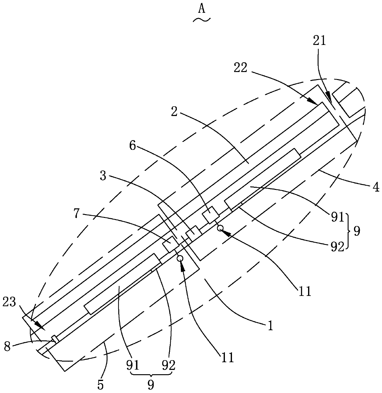
[0021] Please also see Figure 1-2 , the present invention provides a MIMO antenna system 100, including a system ground unit 1, a metal frame 2, a ground line 3, a first antenna 4, a second antenna 5, a first feeding arm 6, a second feeding arm 7, The short-circuit arm 8 and the parasitic unit 9 .

[0022] The system unit 1 is provided with a feed point 11 for feeding the first antenna 4 and the second antenna 5 .

[0023] The metal frame 2 is arranged adjacent to the system ground unit 1 and is separated from the system ground unit 1 to form a clearance area, thereby forming an effective radiation space with the system ground unit 1 .

[0024] The metal frame 2 is provided with a fracture 21 which divides itself to form an open circuit terminal 22 and a short circuit terminal 23 connected to the system ground unit 1, the open circuit terminal 22 and...


PUM


Abstract

The invention provides an antenna system, comprising a system ground unit having a feed point, a metal frame disposed adjacent to the system ground unit, a grounding line extending from the metal frame to the system ground unit and forming a grounding connection, and a first antenna and a second antenna at least having the metal frame as a partial radiator, wherein the metal frame is spaced apartfrom the system ground unit to form a clearance area; the first antenna and the second antenna are electrically connected to the feed point of the system ground unit respectively, and are respectivelydisposed at both sides of the grounding line in a spaced manner and radiate orthogonal modes. Compared with the related art, the antenna system of the invention has a wide frequency band, a good overall aesthetic appearance and high strength.

Description

technical field [0001] The invention relates to an antenna, in particular to a MIMO antenna system used in the field of communication electronic products. Background technique [0002] With the development of mobile communication technology, mobile phones, PADs, notebook computers, etc. have gradually become indispensable electronic products in daily life, and these electronic products have been updated to electronic communication products that add antenna systems to enable communication functions. However, consumers are no longer only satisfied with their application functions, and their requirements for the appearance of the electronic communication products are also constantly increasing. The electronic communication product with a metal casing has a good texture and is durable, so it is welcomed by many consumers. [0003] Because electromagnetic waves cannot penetrate metal, it is not conducive to the radiation of the antenna system. When designing the electronic commu...

Claims


Application Information

Patent Timeline
Patent Type & Authority Applications(China)
IPC IPC(8): H01Q1/24H01Q1/36H01Q1/44H01Q1/48H01Q1/50H01Q1/52H01Q5/10H01Q5/385H01Q21/00H01Q25/04
Inventor 武景
Owner AAC TECH NANJING
Learn More