Dust-proof ventilation power control cabinet

A power control cabinet and dust-proof technology, which is applied in the cooling/ventilation of substation/switchgear, substation/power distribution device shell, etc., can solve the problem of unable to meet the needs of power equipment installation, and the internal space of the cabinet cannot be adjusted and installed The frame structure cannot be adjusted, etc., to achieve the effects of prolonging life, rapid heat dissipation, and reducing maintenance times

Active Publication Date: 2019-05-10
昆明平炜电气设备有限公司
View PDF4 Cites 6 Cited by
  • Summary
  • Abstract
  • Description
  • Claims
  • Application Information

AI Technical Summary

Problems solved by technology

However, the structure of the power control cabinet in the prior art is relatively single, and most of them are a single cabinet structure. Requirements for installation of different electrical equipment

Method used


Image

  • Dust-proof ventilation power control cabinet
  • Dust-proof ventilation power control cabinet
  • Dust-proof ventilation power control cabinet

Examples


specific Embodiment approach 1

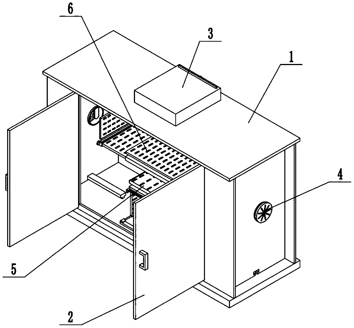
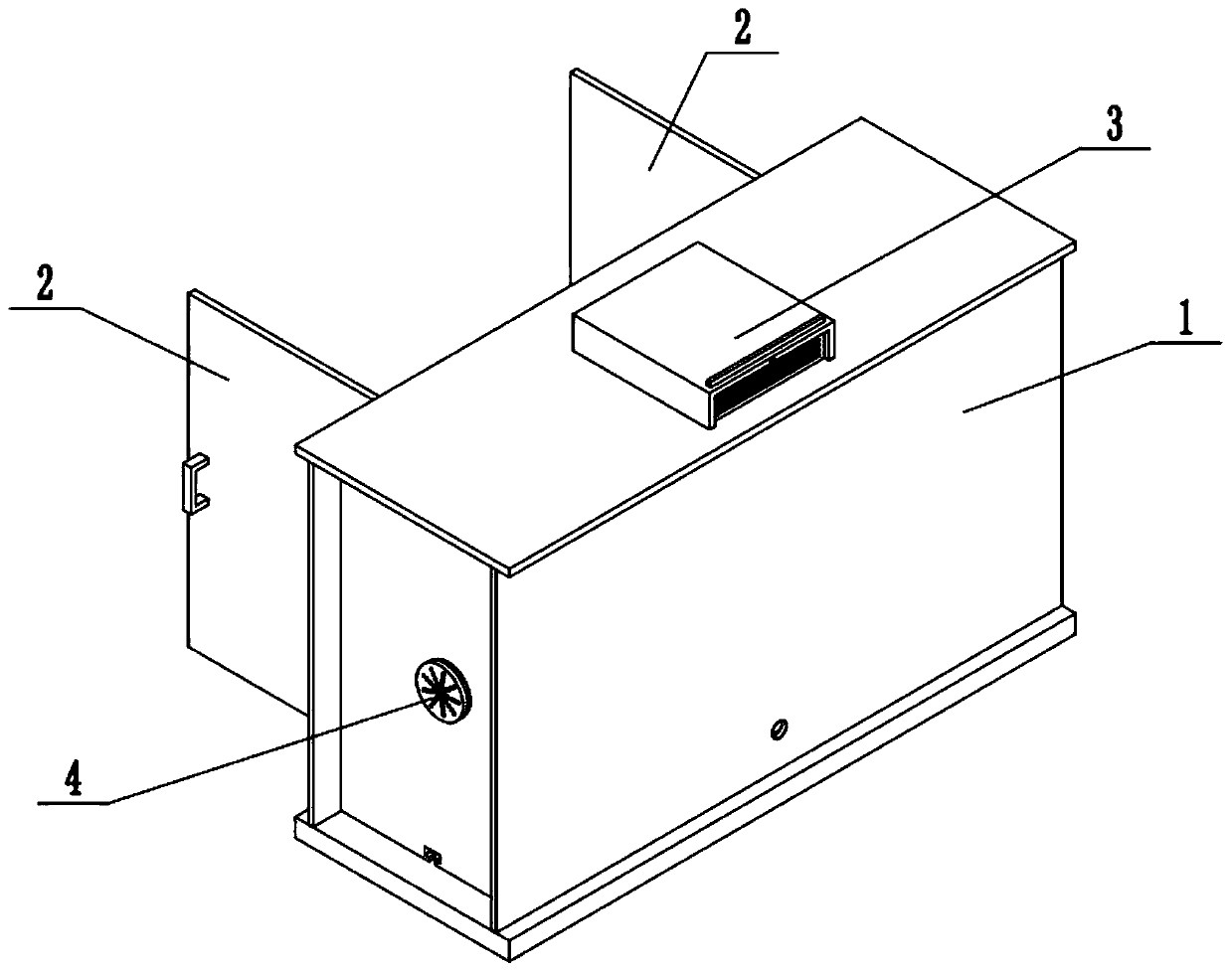
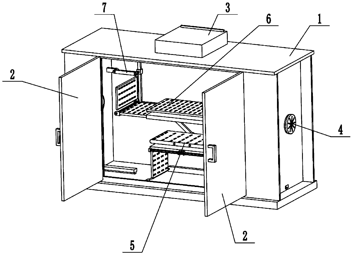
[0027] Such as Figure 1-9 As shown, a dust-proof and ventilated power control cabinet includes a cabinet body 1, a door panel 2, a dust-proof intake mechanism 3, an exhaust ventilation mechanism 4, a lower mounting frame 5, an upper mounting frame 6 and a push-pull frame 7. The cabinet Body 1 includes top board 1-1, bottom board 1-2, cabinet door board 1-3, back board 1-4, side board 1-5 and T-shaped slide rail 1-6; said cabinet door board 1-3 and back board 1 -4 are respectively fixedly connected to the front and rear ends of the top surface of the bottom plate 1-2; the middle end of the top surface of the bottom plate 1-2 is fixedly connected to the left and right two T-shaped slide rails 1-6; Two side plates 1-5 are respectively slidably connected to a T-shaped slide rail 1-6; the top surface, front side, bottom surface and rear side of the side plate 1-5 are respectively connected with the top plate 1-1, the cabinet The door panel 1-3, the bottom panel 1-2 and the back p...

specific Embodiment approach 2

[0029] Such as Figure 1-9 As shown, the backboard 1-4 is provided with cable through holes. The cable through hole is used for external connection of the cables of the electric equipment installed in the cabinet body 1 .

specific Embodiment approach 3

[0030] Such as Figure 1-9 As shown, the dust-proof air intake mechanism 3 includes an air intake box 3-1 and a dust blocking filter plate 3-2; the air intake box 3-1 is fixedly connected on the top plate 1-1, and the air intake box 3-1 A plurality of air intake holes are connected; the rear side and the bottom surface of the air intake box 3-1 are hollow structures; the rear end of the top surface of the air intake box 3-1 is provided with a rectangular through hole; the dust blocking filter plate 3-2 Slip-fit ​​connection in the rectangular through-hole.

[0031] When the dust-proof air intake mechanism 3 is in use, when the exhaust ventilation mechanism 4 works, when the exhaust ventilation mechanism 4 extracts the hot air inside the cabinet body 1, the outside air can enter into the air intake box 3-1. into the cabinet body 1 through the air intake hole to complete the discharge of hot air and the entry of normal temperature air, and when the outside air enters the air in...


PUM


Abstract

The invention relates to a power control cabinet, in particular to a dust-proof ventilation power control cabinet. The dust-proof ventilation power control cabinet comprises a cabinet body, a door plate, a dustproof air inlet mechanism, an exhaust ventilation mechanism, a lower mounting frame, an upper mounting frame and a push-pull frame, wherein the cabinet body comprises a top plate, a bottom plate, a cabinet door plate, a back plate, side plates and T-shaped sliding rails; the cabinet door plate and the back plate are respectively fixedly connected at the front and rear ends of the top surface of the bottom plate; the middle end of the top surface of the bottom plate is fixedly connected with the left and right T-shaped sliding rails; two side plates are arranged, and the two side plates are respectively connected to a T-shaped sliding rail in a sliding fit manner. According to the scheme of the invention, the lower mounting frame and the upper mounting frame which can perform deformation adjustment are arranged inside the power control cabinet, the structures of the lower mounting frame and the upper mounting frame can be adjusted according to the mounting requirements, and the mounting requirements of different power equipment can be conveniently met; and moreover, when the structures of the lower mounting frame and the upper mounting frame are adjusted, the space insidethe cabinet body can be driven to change, so that the cabinet body has enough space to install power equipment.

Description

technical field [0001] The invention relates to a power control cabinet, in particular to a dustproof and ventilated power control cabinet. Background technique [0002] With the continuous development of the social economy and the increasing level of electrification, the installation and use of power facilities has spread to every corner of the society and has become a necessary facility for urban and rural production and operation. Power control cabinets are often used in power systems or telecommunication systems to place power. Equipment or professional electrical wiring use. However, the structure of the power control cabinet in the prior art is relatively single, and most of them are a single cabinet structure. The needs of different electrical equipment installations. Contents of the invention [0003] The purpose of the present invention is to provide a dust-proof and ventilated power control cabinet, which can effectively solve the problems of the power control ...

Claims


Application Information

Patent Timeline
Patent Type & Authority Applications(China)
IPC IPC(8): H02B1/30H02B1/28H02B1/56
Inventor 李振平宋天娇
Owner 昆明平炜电气设备有限公司
Why Eureka
Try Eureka