Double-workbench high-speed numerical control milling machine
A dual-table, CNC milling technology, applied in the field of CNC milling, can solve the problem of not being able to fix all at once, and achieve the effect of improving overall work efficiency, improving processing efficiency, and facilitating installation requirements
- Summary
- Abstract
- Description
- Claims
- Application Information
AI Technical Summary
Problems solved by technology
Method used
Image
Examples
Embodiment 1
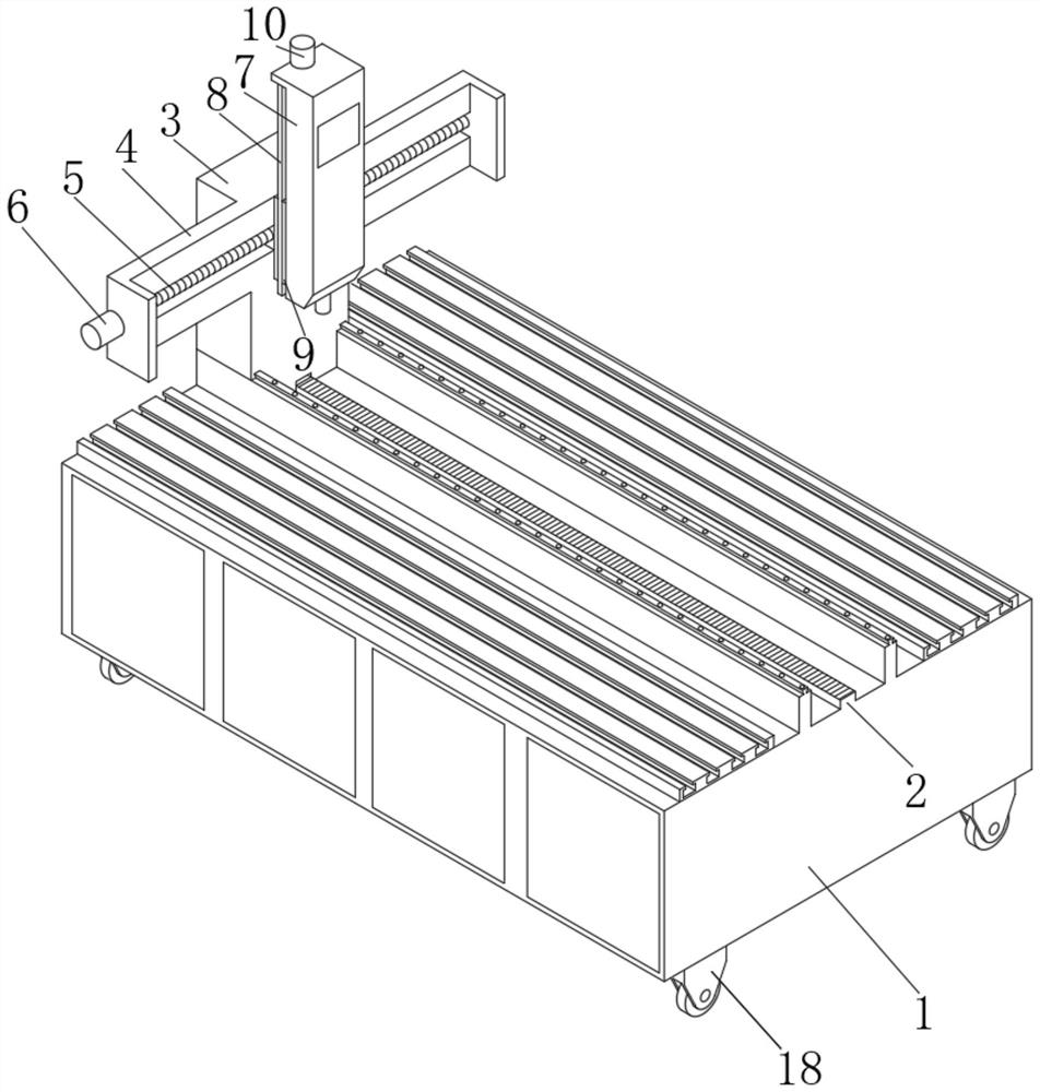
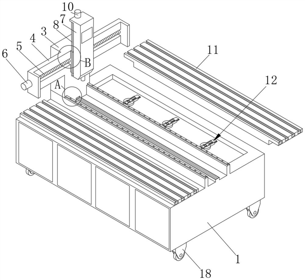
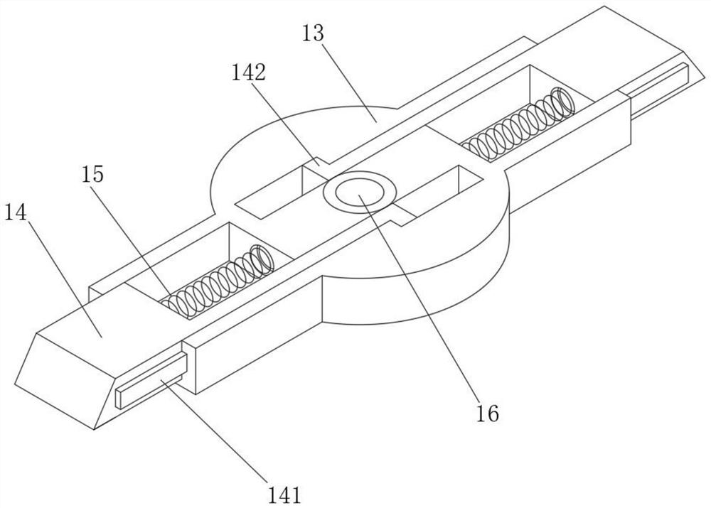
[0024] Embodiment 1: When the workbench body 11 needs to be installed, the present invention provides such figure 1 , figure 2 , image 3 , Figure 4 , Image 6 , Figure 7 A double workbench high-speed CNC milling shown includes a workbench body 1 and a workbench body 11 symmetrically installed at the top of the workbench body 1. The top of the workbench body 1 forms a matching cavity through two isolation plates. Cooperate with the installation frame 3 installed in the cavity, the bottom of the installation frame 3 is equipped with a transmission wheel, the outer edge of the transmission wheel meshes with the top of the transmission plate 2, and the two ends of the top of the installation frame 3 are symmetrically fixed with an unfolding frame 4. One side of the frame 4 is provided with a sliding cavity, and a mounting plate 9 for the processing box 7 is installed in the sliding cavity, and a threaded rod 5 is provided for rotation in the sliding cavity, and the mountin...
Embodiment 2
[0030] Embodiment 2: when the work frame body 1 needs to be moved to the desired position, the present invention provides figure 1 , figure 2 , Figure 5 As shown in a double-table high-speed CNC milling machine, two moving cavities are symmetrically opened at the bottom of the work frame body 1, and two hinge rods 20 are symmetrically hinged in the moving cavity, and the bottom of the hinge rod 20 is installed with Universal wheel 18, the transmission structure 19 that auxiliary universal wheel 18 stretches out and moves is installed in the moving chamber.
[0031] Specifically, the transmission structure 19 includes a mounting box 23 installed in the moving cavity and a transmission rod 22 mounted on the mounting box 23 for lateral rotation. prop up, so as to facilitate the overall movement of the larger work frame body 1, improve the overall movement effect of the milling machine, and facilitate the cleaning of the working impurities at the bottom of the milling machine ...
PUM
 Abstract
Description
Claims
Application Information
 - R&D
- Intellectual Property
- Life Sciences
- Materials
- Tech Scout
- Unparalleled Data Quality
- Higher Quality Content
- 60% Fewer Hallucinations
Browse by: Latest US Patents, China's latest patents, Technical Efficacy Thesaurus, Application Domain, Technology Topic, Popular Technical Reports.
© 2025 PatSnap. All rights reserved.Legal|Privacy policy|Modern Slavery Act Transparency Statement|Sitemap|About US| Contact US: help@patsnap.com


