Fault diagnosis and processing method for current sensor of permanent magnet synchronous motor control system

A permanent magnet synchronous motor and current sensor technology, applied in control systems, vector control systems, motor generator control, etc., can solve problems such as poor effect accuracy, inability to run when stopped, and out-of-control electric vehicles, so as to improve the driving experience. , to ensure the effect of safe driving

Active Publication Date: 2019-05-10
SHANGHAI DAJUN TECH
View PDF5 Cites 8 Cited by
  • Summary
  • Abstract
  • Description
  • Claims
  • Application Information

AI Technical Summary

Problems solved by technology

[0003] In the existing electric vehicle motor control system, two-phase current sensors are usually used for current closed-loop control. When any current sensor fails, the system is not easy to detect the sensor failure, and the electric vehicle will inevitably lose control or stop and cannot run; Some use three-phase current sensors to judge whether there is a current sensor fault according to whether the algebraic sum of the three-phase stator currents of the motor is zero. This method can only detect the current sensor fault, but cannot locate the specific faulty current sensor, and after the fault The vehicle cannot continue to drive. Usually, in this method, after judging the failure of the current sensor sensor, the motor control strategy of torque and speed is realized by changing the voltage and frequency applied to the motor, but its torque control effect is better than that of normal vector control. The accuracy of the control effect is poor, and the driving experience is greatly reduced

Method used


Image

  • Fault diagnosis and processing method for current sensor of permanent magnet synchronous motor control system
  • Fault diagnosis and processing method for current sensor of permanent magnet synchronous motor control system
  • Fault diagnosis and processing method for current sensor of permanent magnet synchronous motor control system

Examples


Embodiment Construction

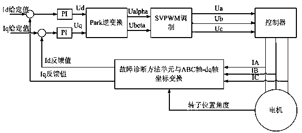
[0031] Example figure 1 and figure 2 As shown, the permanent magnet synchronous motor control system adopts the PI vector control system. The motor three-phase current IA, IB, and IC output the actual control Id feedback value and Iq feedback value after passing through the fault diagnosis method unit. The deviation of the value is input into the PI controller and then outputs Ud and Uq; Ud and Uq are converted into Ualpha and Ubeta after Park inverse transformation, and then output Ua, Ub, and Uc through SVPWM modulation to act on the motor controller.

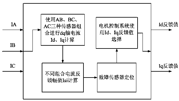
[0032] Such as figure 2 As shown, in the above permanent magnet synchronous motor control system, the current sensor fault diagnosis and processing method includes the following steps:

[0033] Step 1. Three current sensors are used to sample the three-phase stator current of the motor respectively to form a closed-loop vector control system. The three-phase current of the stator is obtained in real time through the three...


PUM


Abstract

The invention discloses a fault diagnosis and processing method for a current sensor of a permanent magnet synchronous motor control system; according to the method, three current sensors are used forcontrolling the motor, and when the sum of three-phase stator current is detected to be not zero, it is judged that a certain phase of current sensor suffers from a fault at the moment; through IA and IB two-phase stator current coordinate transformation, dq axis currents Id1 and Iq1 are obtained; IA and IC two-phase stator current coordinate transformation is carried out to obtain dq axis currents Id2 and Iq2; through IB, and IC two-phase stator current coordinate transformation is carried out to obtain dq axis currents Id3 and Iq3, and then three current amplitude feedback values influencedby two-phase currents are established; the current feedback values are used to position to a specific current sensor of a fault, and the maximum output power is reduced; the two-phase current sensorsare used for controlling the motor, so that a vehicle runs in a limp mode. According to the method, potential safety hazards caused by faults of the stator current sensors are solved, and a limp modeof the vehicle after a fault is provided, so that the safe driving of the vehicle is ensured, and the driving and riding experience is improved.

Description

technical field [0001] The invention relates to the field of electric vehicle motor control, in particular to a current sensor fault diagnosis and processing method of a permanent magnet synchronous motor control system. Background technique [0002] With the development of science and technology and the needs of environmental protection, electric vehicles have become the future development trend. The torque control of electric vehicles is realized by the current closed-loop control of the motor control system. At present, the electric vehicle motor control system generally uses two current sensors to collect current information, and performs coordinate transformation on the measured current information, and uses it as the feedback of the current loop. Finally, the closed-loop control of the system is realized. But when the current sensor fails, if the electric vehicle motor control system continues to run, the vehicle will be out of control, and the sudden stop of the vehi...

Claims


Application Information

Patent Timeline
Patent Type & Authority Applications(China)
IPC IPC(8): H02P21/00H02P21/14H02P21/22H02P27/08
Inventor 王海鑫丰树帅杜朝辉黄洪剑
Owner SHANGHAI DAJUN TECH
Why Eureka
Try Eureka