
Air-locking feeding device with drying function

A technology of feeding device and air lock, which is applied in the direction of drying, drying machine, drying gas arrangement, etc., can solve the problems of increasing the gap between the blade and the shell, aggravating the wear of the rotating blade, and the large running resistance of the rotating rotor. To achieve the effect of preventing wear and running resistance increase, reducing energy consumption and long service life

Pending Publication Date: 2019-05-14
NANJING XIPU CEMENT ENG GROUP
View PDF7 Cites 2 Cited by
  • Summary
  • Abstract
  • Description
  • Claims
  • Application Information

AI Technical Summary

Problems solved by technology

[0004] At present, the rotary feeding device used does not adopt an effective drying device, which is not suitable for materials with high moisture content, which causes the materials to easily stick to the shell, resulting in changes in the gap between the rotary blade and the shell. On the one hand, Aggravate the wear of the rotary blades, increase the gap between the blades and the shell, and cause serious air leakage; on the other hand, it will also cause high resistance to the rotary rotor, causing the motor to overload and stop, affecting production safety

Method used


Image

  • Air-locking feeding device with drying function
  • Air-locking feeding device with drying function
  • Air-locking feeding device with drying function

Examples


Embodiment Construction

[0020] The present invention will be further illustrated below in conjunction with the accompanying drawings and specific embodiments. This embodiment is implemented on the premise of the technical solution of the present invention. It should be understood that these embodiments are only used to illustrate the present invention and are not intended to limit the scope of the present invention.

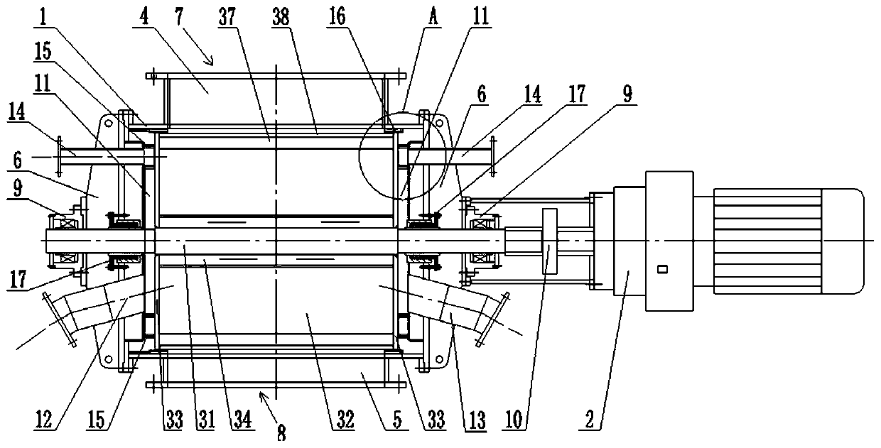
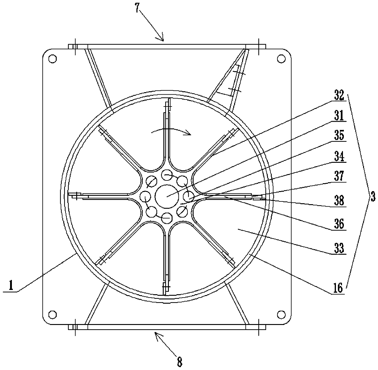
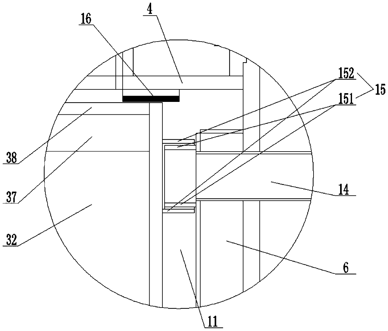
[0021] Such as figure 1 As shown, the embodiment of the present invention provides an airlock feeding device with a drying function, the device includes a housing 1, a power unit 2 and a rotary rotor 3, and the middle part of the rotary rotor 3 is arranged in the housing 1, the upper and lower ends of the shell 1 are respectively provided with an upper end flange 4 and a lower end flange 5, and the two sides of the shell 1 are respectively provided with a side end flange 6, an upper end flange 4, and a lower end flange 5 Both the side flange 6 and the housing 1 are preferably bolted tog...


PUM


Abstract

The invention discloses an air-locking feeding device with a drying function. The device comprises a casing, a power device and a rotary rotor; the rotary rotor comprises a rotating shaft connected with the power device, a plurality of blades arranged on the periphery of the middle of the rotor at intervals, and two end plates fixed between the two side ends of the blades and the rotating shaft correspondingly; a heating channel is defined by the multiple blades, the end plates and the outer surface of the rotating shaft; the end plates on the two sides of the heating channel are each providedwith a plurality of venting holes; spaced air channels are formed by the two end plates and the inner sides of flanges of the two side ends; the air channels communicate with the heating channel through the venting holes; and the outer sides of the two end plates are sequentially provided with a drying air inlet pipe and a drying air outlet pipe which communicate with the air channels. An abrasion-resistant lining plate is convenient to replace, by arranging a drying mechanism, abrasion of material sticking to the rotor and increase of operation resistance are effectively prevented, the system energy consumption is reduced, the service life is longer, and the air-locking feeding device is more environmentally friendly.

Description

technical field [0001] The invention relates to the field of feeding devices, in particular to an air-lock feeding device with a drying function. Background technique [0002] The feeding device is an industrial equipment used in various industries. It is mainly used to transport materials to downstream equipment for corresponding operations. In some applications, it is not only necessary to smoothly transport materials to downstream equipment, but also to It has the function of locking the air, that is, while completing the material transportation, it can minimize the external air from entering the downstream equipment, which will affect the working conditions of the system. [0003] A good air lock effect is directly related to the energy consumption of the entire process system and the stability of the production state. A good air lock effect and low internal wear of the equipment are the main indicators for considering the feeding device. Therefore, reducing the air lea...

Claims


Application Information

Patent Timeline
Patent Type & Authority Applications(China)
IPC IPC(8): B65G53/16B65G53/46B65G53/34F26B21/00
CPCF26B21/00B65G53/16B65G53/46B65G53/34
Inventor 赵玉会苑明华朱宽平曹国锋孙云
Owner NANJING XIPU CEMENT ENG GROUP
Learn More