Gas-collecting hood for gas water heater and gas water heater using gas-collecting hood

A technology of gas water heaters and gas collecting hoods, which is applied in the direction of fluid heaters, combustion methods, exhaust gas devices, etc., which can solve the problems of large exhaust resistance, the opening of the top of the valve plate, and the difficulty of exhausting smoke, so as to achieve enhanced anti-corrosion Wind pressure capacity, reduce exhaust resistance, and reduce the effect of force-bearing area

Inactive Publication Date: 2019-05-14
NINGBO FOTILE KITCHEN WARE CO LTD
View PDF3 Cites 7 Cited by
  • Summary
  • Abstract
  • Description
  • Claims
  • Application Information

AI Technical Summary

Problems solved by technology

The disadvantages of this structure are: 1. When exhausting, the flue gas pressure is not only greater than the external wind pressure, the overall gravity of the valve plate and the positioning support seat of the valve plate, but also because the positioning bracket is slidingly connected with the inner wall of the air inlet / air outlet , it is also necessary to overcome the friction between the positioning bracket and the inner wall of the air inlet / outlet
If the exhaust resistance is large, there will still be a phenomenon that the valve plate is stuck or the opening is extremely small, resulting in the phenomenon that the smoke cannot be completely discharged; 2. The positioning bracket is slidingly connected with the inner wall of the air inlet / air outlet, and a pulley and a chute need to be installed and other auxiliary accessories, the structure is complex
[0005] In addition, the current anti-backflow device on the gas collecting hood generally adopts the vertical smoke exhaust method as shown above, and the exhausted smoke flow will be directly impacted by the external wind force, resulting in a large exhaust resistance and difficult to discharge the smoke. There is still the phenomenon of smoke stagnation in the room

Method used


Image

  • Gas-collecting hood for gas water heater and gas water heater using gas-collecting hood
  • Gas-collecting hood for gas water heater and gas water heater using gas-collecting hood
  • Gas-collecting hood for gas water heater and gas water heater using gas-collecting hood

Examples


Embodiment Construction

[0030] The present invention will be further described in detail below in conjunction with the accompanying drawings and embodiments.

[0031] like Figure 1-7 Shown is a preferred embodiment of the present invention.

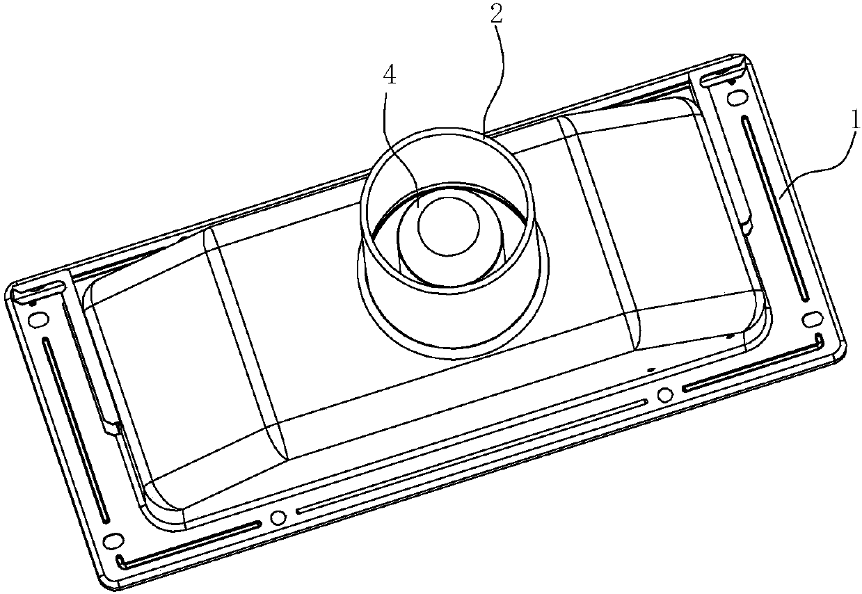
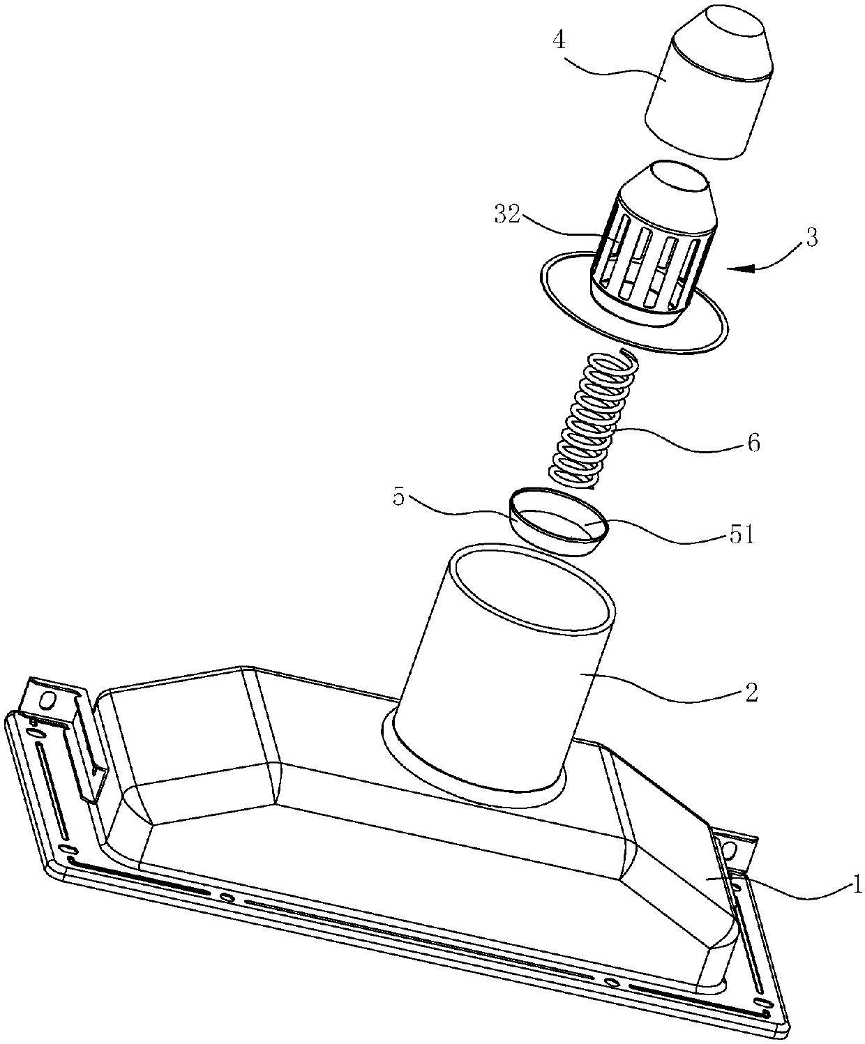
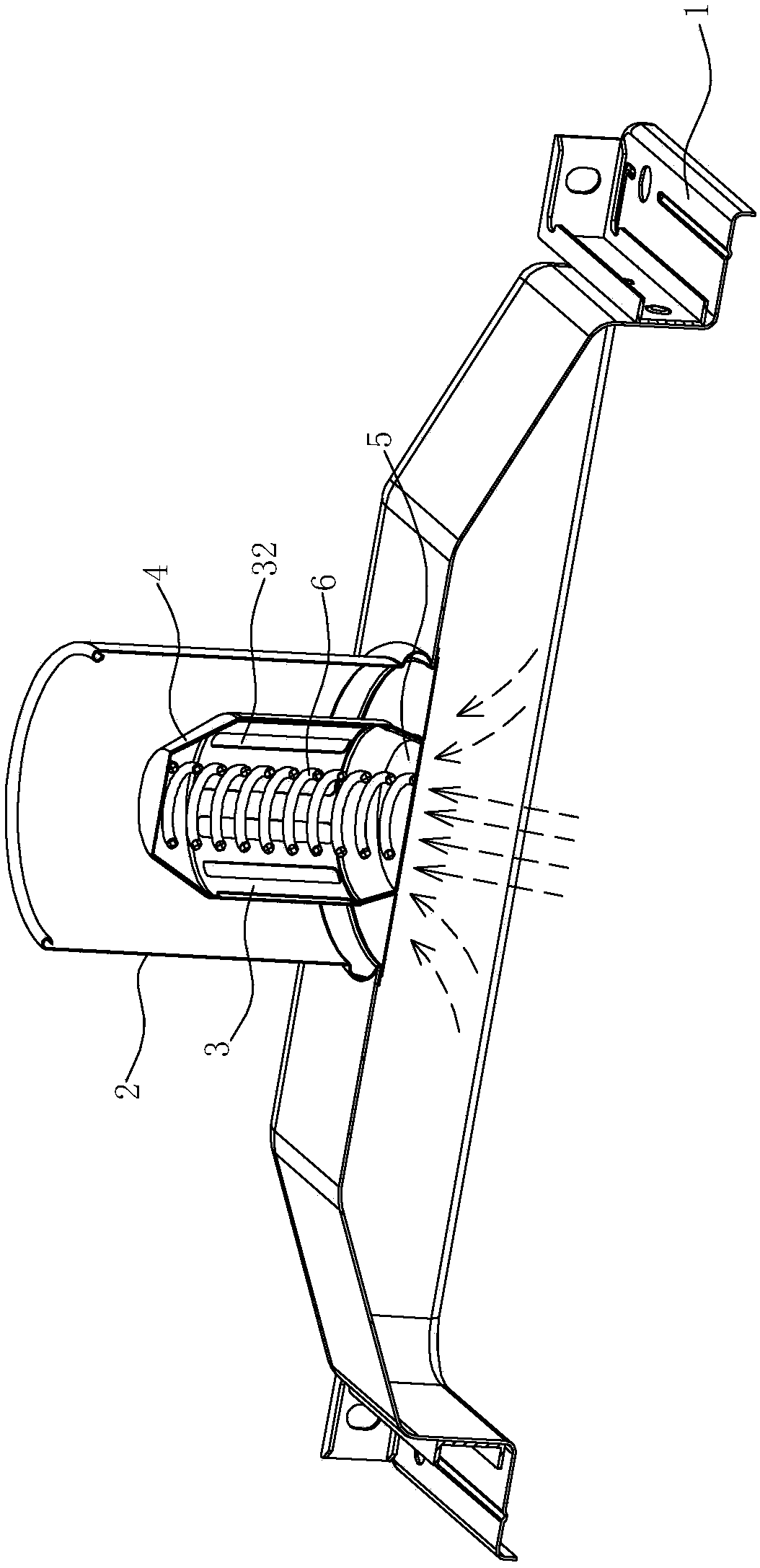
[0032] The gas collecting hood for a gas water heater includes a hood body 1 and a vertical exhaust pipe 2 arranged on the top of the hood body 1, and the exhaust pipe 2 is connected with a pipe leading to the outside to discharge smoke. Wherein the exhaust pipe 2 is provided with an air guide cylinder 3, the lower end air inlet 31 of the air guide cylinder 3 communicates with the inner cavity of the cover body 1, and the side peripheral wall of the air guide cylinder 3 is provided with at least two exhaust pipes at intervals in the upper direction. Hole 32 , the exhaust hole 32 extends axially along the side peripheral wall of the air guide tube 3 . A sleeve 4 with an open bottom and a closed top is provided outside the air guide tube 3, the sleeve 4 can mov...


PUM


Abstract

The invention relates to a gas-collecting hood for a gas water heater. The gas-collecting hood comprises a hood body and a vertical gas-exhausting pipe arranged at the top of the hood body and is characterized in that: a gas guide drum is arranged in the gas-exhausting pipe; a gas inlet formed in the lower end of the gas guide drum is communicated with an inner chamber of the hood body; at least one gas-exhausting hole is formed in the side wall of the gas guide drum; a sleeve, of which the bottom is opened and the top is closed, is arranged on the outer side of the gas guide drum in a sleeving manner; and the sleeve can move up and down relative to the gas guide drum, and can move downward to fully cover the gas-exhausting hole and upward to expose at least part of the gas-exhausting hole. Compared with a manner of vertical fume exhausting, fume exhausting from the side wall of the gas guide drum can alleviate the impact of external wind force, reduces the resistance to the fume pressure, and allows fume to be exhausted easily.

Description

technical field [0001] The invention belongs to the field of gas water heaters, and in particular relates to a gas collecting hood for a gas water heater and a gas water heater using the gas collecting hood. Background technique [0002] With the advantages of high thermal efficiency, fast heating speed, stable temperature regulation, and continuous use by multiple people, gas water heaters are still the first choice of many consumers. The safety of gas water heaters is also the most concerned issue. The main cause of safety accidents is the CO and SO produced by the combustion system. 2 Toxic and harmful gases will pollute the indoor air. To avoid poisoning accidents caused by toxic and harmful gases in the flue gas, the fundamental measure is to discharge the flue gas outside to keep the indoor air clean and hygienic. Therefore, it is necessary to install a gas collecting hood on the gas water heater to serve as CO and SO 2 Collection devices for toxic and harmful gas po...

Claims


Application Information

Patent Timeline
Patent Type & Authority Applications(China)
IPC IPC(8): F24H9/00F23J11/00
Inventor 刘筱倩谭洵金晶梁稳茅忠群诸永定周高云
Owner NINGBO FOTILE KITCHEN WARE CO LTD
Why Eureka
Try Eureka