Debris flow area directional blasting equipment and method in a mine

A technology of directional blasting and debris flow, which is applied in the field of mine blasting to achieve the effect of smooth and smooth excavation surface, small damage impact, and saving engineering investment.

Active Publication Date: 2021-06-11
武汉山友爆破科技工程有限公司
View PDF5 Cites 0 Cited by
  • Summary
  • Abstract
  • Description
  • Claims
  • Application Information

AI Technical Summary

Problems solved by technology

[0004] At present, there is no precedent for directional blasting in the debris flow accumulation area of ​​mines at home and abroad. How to blast in the debris flow accumulation body of mines safely, effectively, economically and rationally is an important topic worthy of research

Method used


Image

  • Debris flow area directional blasting equipment and method in a mine
  • Debris flow area directional blasting equipment and method in a mine
  • Debris flow area directional blasting equipment and method in a mine

Examples


Embodiment 1

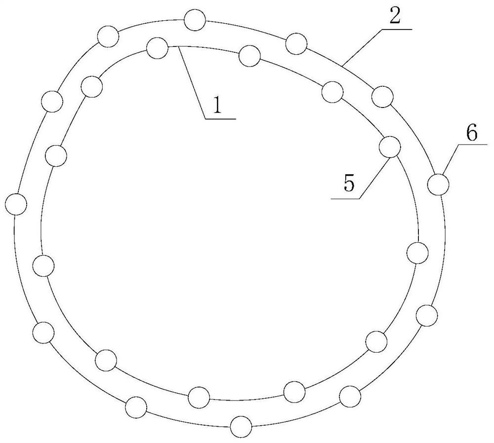
[0035] This embodiment provides a directional blasting equipment in the debris flow area of ​​a mine, which includes a first contour line 1 and a second contour line 2 depicted on the mine, and the first contour line 1 is provided with a plurality of intervals. The first blast hole and the second blast hole are provided with a plurality of second blast holes arranged at intervals on the second contour line 2. The first blast hole is provided with a plurality of first blast slots arranged at intervals from top to bottom. There are a plurality of second blasting slots arranged at intervals from top to bottom. The drilling diameter expanding device 3 or blasting device is placed in the first blasting slot, and the drilling diameter expanding device 3 or blasting device is placed in the second blasting slot. device 4.

[0036] In the present invention, blasting is carried out in the area of ​​the first contour line first, and then blasting in the area of ​​the second contour line,...

Embodiment 2

[0057] The distance between the first contour line 1 and the second contour line 2 in the embodiment is set to 0.3m. The slide bar is a cylindrical structure. On the first contour line 1, the distance between two adjacent first blast holes is 0.35m. On the second contour line 2, the distance between two adjacent second blast holes is 0.7m.

[0058] In actual operation, when the distance between two adjacent first blast holes is half of the distance between two adjacent second blast holes, the blasting effect is the best.

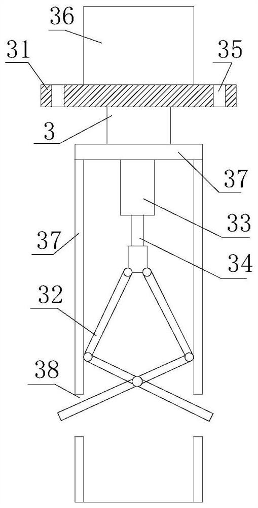
[0059] Drilling device 3 and blasting device 4 still adopt the same structure and the same working principle as embodiment 1, specifically as follows:

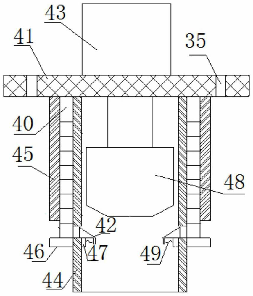
[0060] The blasting device 4 includes a fixed plate 41 and a wedge assembly 42. The upper end of the fixed plate 41 is equipped with a blasting cylinder 43 and a sling connection hole 35. The lower end of the fixed plate 41 is connected with an inner cylinder 44 and an outer cylinder 45. The inner cylinder...


PUM


Abstract

The invention belongs to the technical field of mine blasting, and discloses a directional blasting device in a debris flow area of ​​a mine. It includes the first contour line and the second contour line carved on the mine. The first contour line is provided with a plurality of first blast holes arranged at intervals, and the second contour line is provided with a plurality of interval arranged blast holes. For the second blast hole, the first blast hole is provided with a plurality of first blast slots arranged at intervals from top to bottom, and the second blast hole is provided with a plurality of second blast slots arranged at intervals from top to bottom. A drilling diameter expanding device or blasting device is placed in the first blasting slot, and a drilling diameter expanding device or blasting device is placed in the second blasting slot. The present invention can place different volumes of explosive charges in different blasting devices according to requirements, thereby reducing the amount of overburden and undercut. The invention also relates to the directional blasting method of the directional blasting equipment in the debris flow area of ​​the mine.

Description

technical field [0001] The invention belongs to the technical field of mine blasting, and in particular relates to directional blasting equipment in a debris flow area of ​​a mine. The invention also relates to a directional blasting method of the directional blasting equipment in the debris flow area of ​​the mine. Background technique [0002] When the explosive explodes in the blast hole, it will generate powerful shock waves and high-pressure gas, which will violently impact the rock mass around the blast hole, causing the surrounding rock to break or crack. When excavation and blasting are carried out within the limited contour range of the mine, on the one hand, it is required that the boundary of the blasting excavation should match the contour line of the design as much as possible, and no over-excavation or under-excavation should occur. Keep it as intact as possible. [0003] Debris flow in the mine, the geological hazard body is in a scattered structure, mainly ...

Claims


Application Information

Patent Timeline
Patent Type & Authority Patents(China)
IPC IPC(8): F42D1/00F42D3/04
Inventor 高广义桂谦
Owner 武汉山友爆破科技工程有限公司
Why Eureka
Try Eureka