Check patentability & draft patents in minutes with Patsnap Eureka AI!

Steel bar image scanning detector

An image scanning and detector technology, which is applied in the field of scanning detectors, can solve problems such as the inability of steel bar scanning detectors to visually display steel bar images, and achieve the effect of improving efficiency

Pending Publication Date: 2019-05-14
王桂亮
View PDF9 Cites 0 Cited by
  • Summary
  • Abstract
  • Description
  • Claims
  • Application Information

AI Technical Summary

Problems solved by technology

[0010] In order to solve the problem that the steel bar scanning detector in the prior art cannot visually display the image of the steel bar in the concrete, the present invention provides a steel bar image scanning detector, the purpose of which is to use section scanning, and obtain the result after scanning It is the electromagnetic reflection signal of steel bars at all points on a surface. After signal processing, the real image of steel bars can be obtained, and the image of steel bars can be displayed while scanning. What you see is what you get.

Method used


Image

  • Steel bar image scanning detector
  • Steel bar image scanning detector
  • Steel bar image scanning detector

Examples


Embodiment

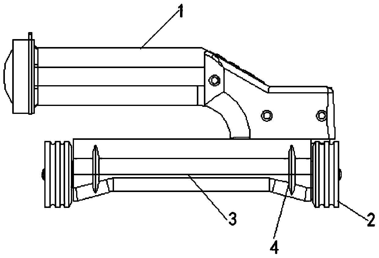
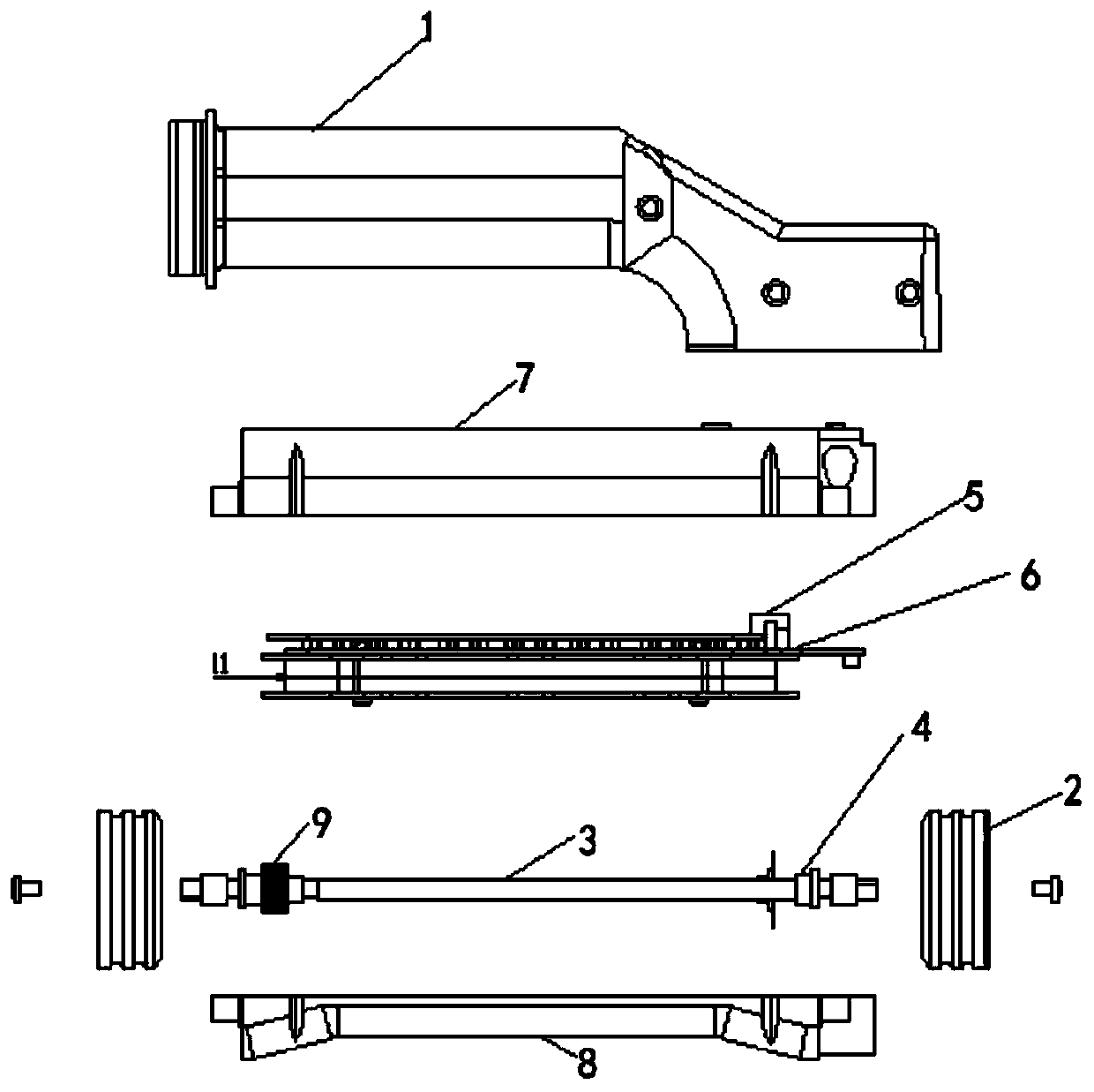
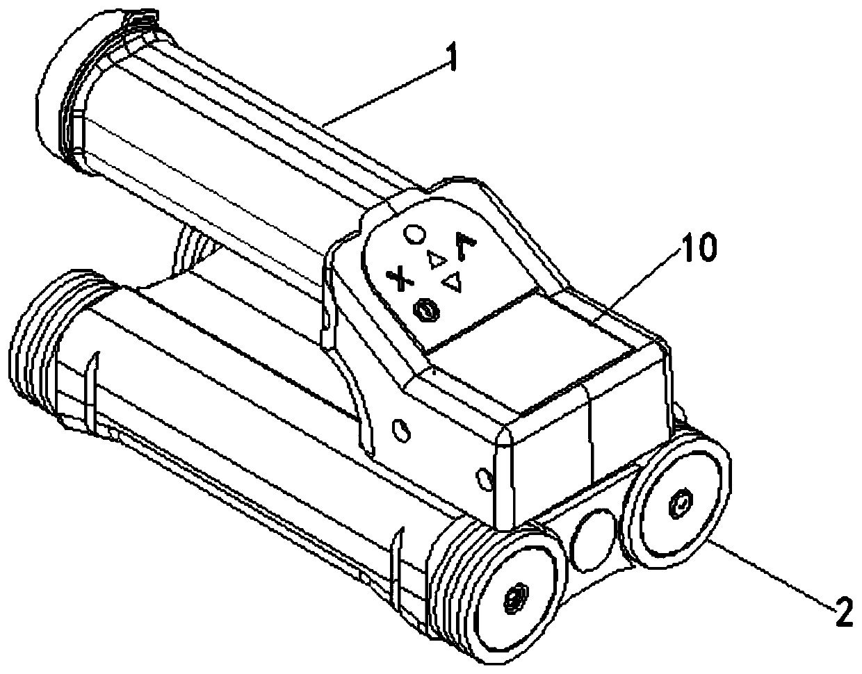
[0026] Embodiment: a kind of steel bar image scanning detector disclosed by the present invention, refer to Figure 3-Figure 6 (In order to be able to see the internal structure clearly, Figure 4-Figure 6 Partial section processing has been done), including a probe 1, a 480*320 dot matrix TFT color liquid crystal display 10 is installed on the probe, a CPU 11 is fixed inside the probe, a pulse generator 12 electrically connected to the CPU, and a pulse generator Electrically connected with a pulse driver 13, a main coil 14 is installed on the bottom surface of the probe, the main coil receives the pulse signal from the pulse driver and sends out the pulse signal, and an induction coil 15 for inducting the main coil is also installed in the space surrounded by the main coil. The induction coil is electrically connected with a detection amplifier 16, the detection amplifier is connected with the CPU through a multi-channel analog-to-digital converter 17, and the TFT color liqui...


PUM


Abstract

The invention discloses a steel bar image scanning detector. The detector comprises a probe; a 480*320 dot matrix TFT color liquid crystal display is installed on the probe; a CPU and a pulse generator electrically connected with the CPU are fixed in the probe; the pulse generator is electrically connected with a pulse driver; a main coil is installed on the bottom surface of the probe; the main coil receives a pulse signal from the pulse driver and outputs the pulse signal; an induction coil for inducing the main coil is further installed in a space defined by the main coil; the induction coil is electrically connected with a detection amplifier; the detection amplifier is connected with the CPU through a multi-channel analog-digital converter; and the TFT color liquid crystal display isin circuit connection with the CPU. Compared with the prior art, the detector has the advantages that an image of steel bars buried in concrete can be intuitively displayed in real time; the depth, spacing, thickness, direction and distribution conditions of the steel bars can be intuitively displayed; and the efficiency of field steel bar detection is greatly improved.

Description

technical field [0001] The invention belongs to the technical field of scanning detectors, in particular to a steel bar image scanning detector. Background technique [0002] There are two main types of existing steel bar detectors: [0003] The first category: the steel bar detector represented by German Hilti PS200, this product includes two parts: [0004] 1. PS200S probe: [0005] Probe structure and function: Probe 1 has four wheels 2, and every two wheels are connected by shaft 3 (as attached figure 1 , figure 2 shown). The shafts of the pair of wheels are fixed with an encoder disc 4 and pass through the gap of the photoelectric encoder 5 . The rotation of the wheel will drive the code disc to rotate, and the code strip on the code disc cuts the infrared light sent by the photoelectric encoder fixed on the circuit board 6, so that the encoder generates a pulse signal. As the distance signal of the probe movement, it is output to the CPU (central processing unit...

Claims


Application Information

Patent Timeline
Patent Type & Authority Applications(China)
IPC IPC(8): G01D5/36G01B11/00G01V3/10
Inventor 王桂亮
Owner 王桂亮
Features
  • R&D
  • Intellectual Property
  • Life Sciences
  • Materials
  • Tech Scout
  • Unparalleled Data Quality
  • Higher Quality Content
  • 60% Fewer Hallucinations
Learn More