Automatic weighing and pouring device and method for energetic raw material
An automatic weighing and material pouring device technology, applied in the field of pyrotechnics, can solve the problems of low weighing and pouring efficiency, low degree of automation, and great potential safety hazards, so as to improve weighing efficiency and quality, high degree of automation, The effect of improving measurement accuracy
- Summary
- Abstract
- Description
- Claims
- Application Information
AI Technical Summary
Problems solved by technology
Method used
Image
Examples
Embodiment 1
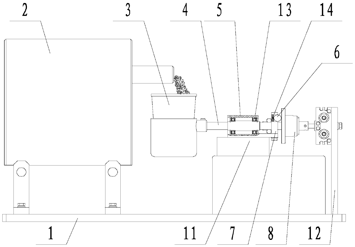
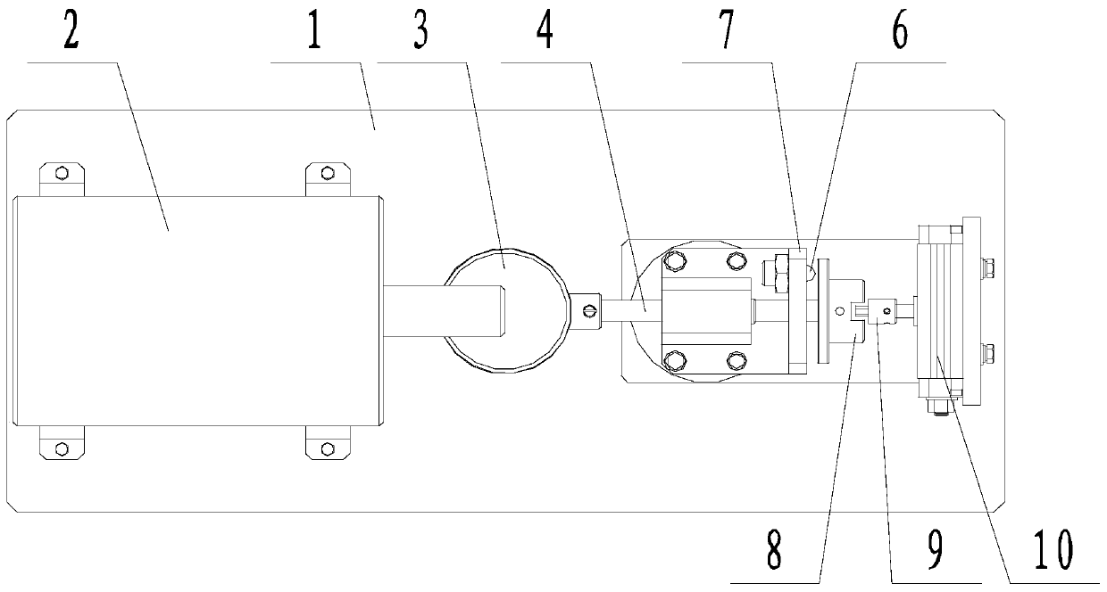
[0035] like figure 1 and figure 2 The shown automatic weighing and discharging device for energetic raw materials includes a feeding mechanism 2, a weighing cup 3 located below the outlet of the feeding mechanism 2, and the weighing cup 3 is fixedly connected to the drive shaft 4, The weighing cup 3 can rotate with the driving shaft 4, and the end of the driving shaft 4 away from the weighing cup 3 is fixedly connected to the shift fork 8; it also includes a rotating device 10, which is used to drive the shifting block 9 to rotate ; The shift fork 8 can rotate with the shift block 9 ; It also includes a load cell 11 , and the load cell 11 is used to monitor the weight change of the weighing cup 3 .
Embodiment 2
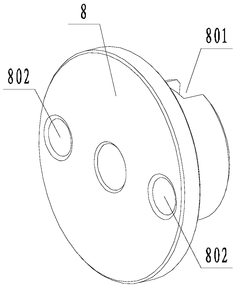
[0037] like Figure 1 to Figure 5 In the shown automatic weighing and discharging device for energetic raw materials, on the basis of Example 1, the drive shaft 4 passes through the bearing seat 5, and a bearing 13 matching the drive shaft 4 is arranged in the bearing seat 5 , the bearing housing 5 is fixed on the load cell 11 . It also includes a mounting plate 1 on which the feeding mechanism 2 , the load cell 11 and the rotating device 10 are all fixed. A through groove 801 is provided on the side surface of the shift fork 8 facing the direction of the shift block 9 , and the shift block 9 is located in the through groove 801 . The width of the through slot 801 is 3-4 mm larger than the width of the shifting block 9 . It also includes a positioning bead 6, and the shift fork 8 is provided with a positioning groove 802 matching the positioning bead 6, and the positioning bead 6 is located on the movement track of the matching positioning groove 802. The positioning bead 6...
Embodiment 3
[0039] A method for automatic weighing and pouring of powder materials, such as Figure 1 to Figure 5 shown, including the following steps:
[0040] (a) The mouth of the weighing cup 3 is upward, and the feeding mechanism 2 feeds the material into the weighing cup 3, and the weight increment of the weighing cup 3 monitored by the load cell 11 is the material weight;
[0041] (b) When the weight of the material in the weighing cup 3 reaches the set value, the feeding mechanism 2 stops discharging, and the rotating device 10 starts to move, driving the shifting block 9 to rotate 180°, and the shifting block 9 drives the shifting fork 8 to rotate 180° At this time, the positioning groove 802 on the shift fork 8 rotates to face the positioning bead 6, and the positioning bead 6 enters the positioning groove 802 under the action of the elastic member; at the same time, the shift fork 8 drives the drive shaft 4 to rotate, so that the weighing cup 3 also rotate 180° in the same dire...
PUM
 Abstract
Description
Claims
Application Information
 - R&D
- Intellectual Property
- Life Sciences
- Materials
- Tech Scout
- Unparalleled Data Quality
- Higher Quality Content
- 60% Fewer Hallucinations
Browse by: Latest US Patents, China's latest patents, Technical Efficacy Thesaurus, Application Domain, Technology Topic, Popular Technical Reports.
© 2025 PatSnap. All rights reserved.Legal|Privacy policy|Modern Slavery Act Transparency Statement|Sitemap|About US| Contact US: help@patsnap.com


