
Directional turning gear

A directional disc and steering wheel technology, which is used in the testing of measuring devices, instruments, and mechanical parts, etc., can solve the problems of non-standard and unified measuring points, prolonged engineering construction period, high labor intensity, etc., to achieve flexible and stable devices, and extended operation. Longevity, the effect of avoiding repeated exploration

Active Publication Date: 2019-05-14
庞子敬
View PDF10 Cites 2 Cited by
  • Summary
  • Abstract
  • Description
  • Claims
  • Application Information

AI Technical Summary

Problems solved by technology

However, the driving methods that most equipment manufacturers can provide now still use the original human lever direct drive and crane traction driving methods, which have poor safety, high labor intensity and low work efficiency.
Even with the emergence of the elastic force couple turning device (China Invention Patent No.: 02135704.8), the passive situation of high labor intensity and low work efficiency has been improved, but due to the lack of orientation device: the rotation azimuth reference is blind, the rotation angle has no reference, and the measuring points are not accurate. Standards are uniform, and accurate data cannot be measured quickly, resulting in repeated invalid labor and prolonging the construction period of the project

Method used


Image

  • Directional turning gear
  • Directional turning gear
  • Directional turning gear

Examples


Embodiment Construction

[0022] With reference to the accompanying drawings, the specific embodiments of the present invention, such as the shape and structure of each component involved, the mutual position and connection relationship between each part, the function and working principle of each part, etc. detailed description.

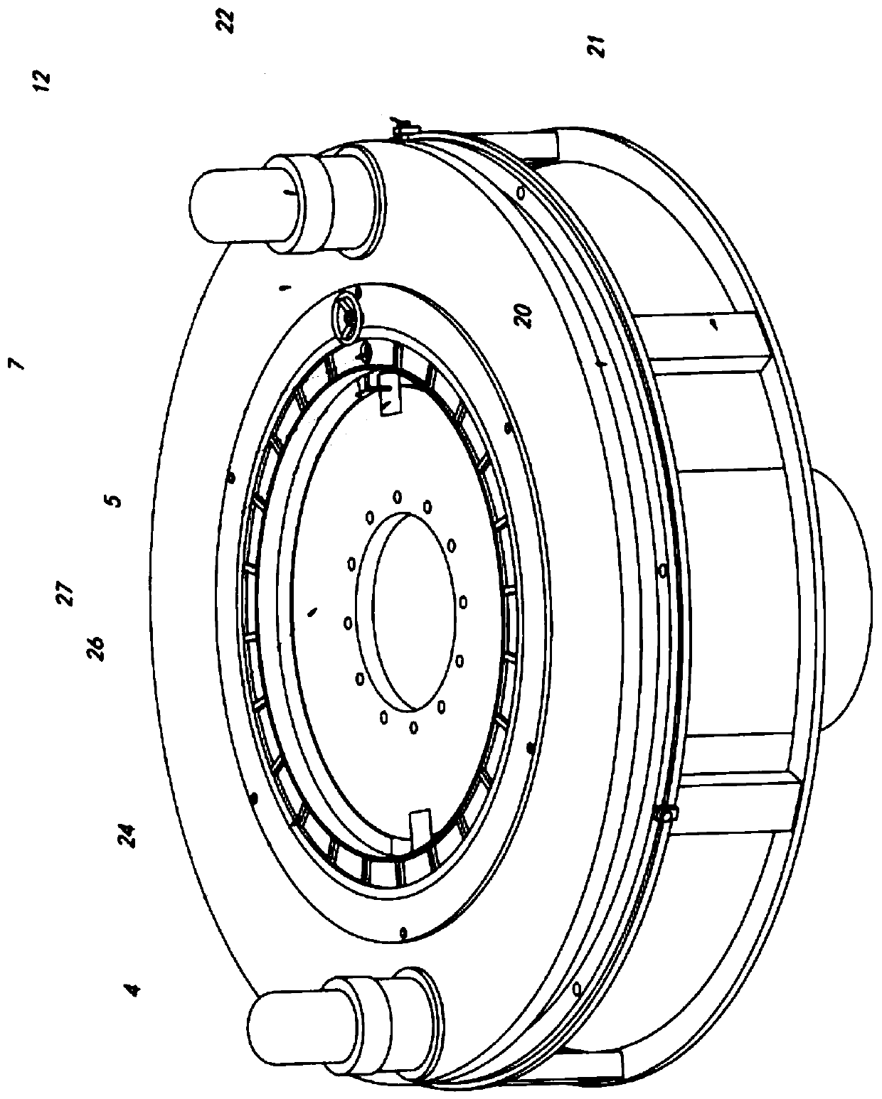
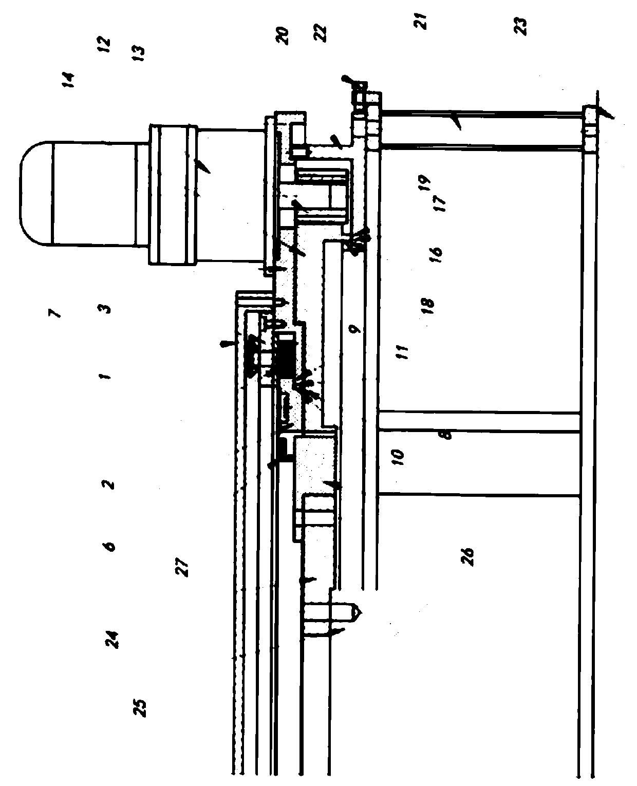
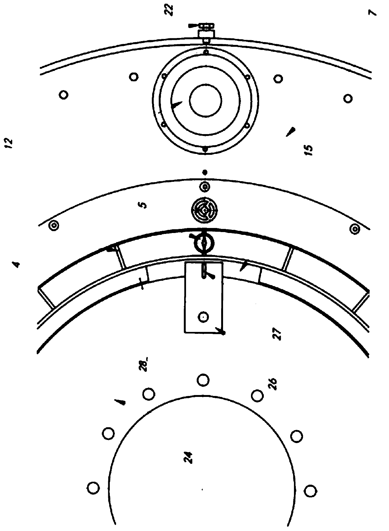
[0023] The working principle of the directional turning device of the present invention is: when the orientation is determined and the power is turned on, the reducer 12 with rotational power assembled in a 180° symmetrical position forms a force couple, and the rotational power can be generated by the motor. The number of reducers can be determined according to the size of the load. The output shaft of the reducer drives the pinion 13 to rotate, and the similarly symmetrically distributed pinions drive the large gear 14 that meshes with it to rotate. Since the large gear is subjected to a pair of balanced tangential forces, the large gear 14 drives the coupling 24 through t...


PUM


Abstract

The invention discloses a directional turning gear. The directional turning gear is provided with a standard orientation by a compass and drives a rotor of rotating equipment through an elastic couple, such as a rotor of a hydroelectric generator. The directional turning gear comprises a supporting frame, a machine shell, reduction gears with rotating power assembled at a 180 degree symmetrical position, and the rotating power of the reducers is transmitted to a coupler through a transmission mechanism; and the directional turning gear is characterized in that a directional device for specifying directions is arranged on the directional turning gear, the directional device is matched with an indicating finger and a graduated disc, wherein the indicating finger and the graduated disc can berelatively rotary fit and identify a rotating starting direction and a rotating angle of the coupler. The directional turning gear has practical significance for fast, accurately and effectively measuring shafting swing data, analyzing and judging change rules of shafting swing between a last final record and an original record before the overhaul, analyzing, comparing and standardly judging a unit and throw of the unit, shortening the time limit for a project, prolonging the operation life of the unit, improving working conditions and improving working efficiency.

Description

technical field [0001] The directional turning device of the present invention is a power equipment that is given a reference orientation by a compass and drives a rotor of a rotating equipment, such as a hydro-generator rotor, by means of an elastic force couple, so as to realize the shafting adjustment process and the decent work of the personnel. Background technique [0002] To adjust the center of the shafting of the hydro-generator set, the rotor needs to be driven by external force in order to check the radial swing value of each section of the shafting at each angle. It is necessary to stop and debug during the initial installation and use for a period of time, so as to make it work in the best state . This requires that the driving speed is uniform and stable, the stopping point is accurate, and at each stopping point, the rotor is placed in a fully free state to eliminate the interference of external force on the rotor, and at the same time, it is required to be co...

Claims


Application Information

Patent Timeline
Patent Type & Authority Applications(China)
IPC IPC(8): G01M13/00
Inventor 庞子敬
Owner 庞子敬
Learn More