Eureka AIR delivers breakthrough ideas for toughest innovation challenges, trusted by R&D personnel around the world.

Field simple soil runoff observation area

A technology for observing plots and soil, applied in the field of water and soil loss monitoring, can solve the problems of high construction cost, large soil disturbance, and difficult to repair, and achieve the effects of low cost, less earthwork, and easy portability

Pending Publication Date: 2019-05-14
BEIJING FORESTRY UNIVERSITY
View PDF0 Cites 3 Cited by
  • Summary
  • Abstract
  • Description
  • Claims
  • Application Information

AI Technical Summary

Problems solved by technology

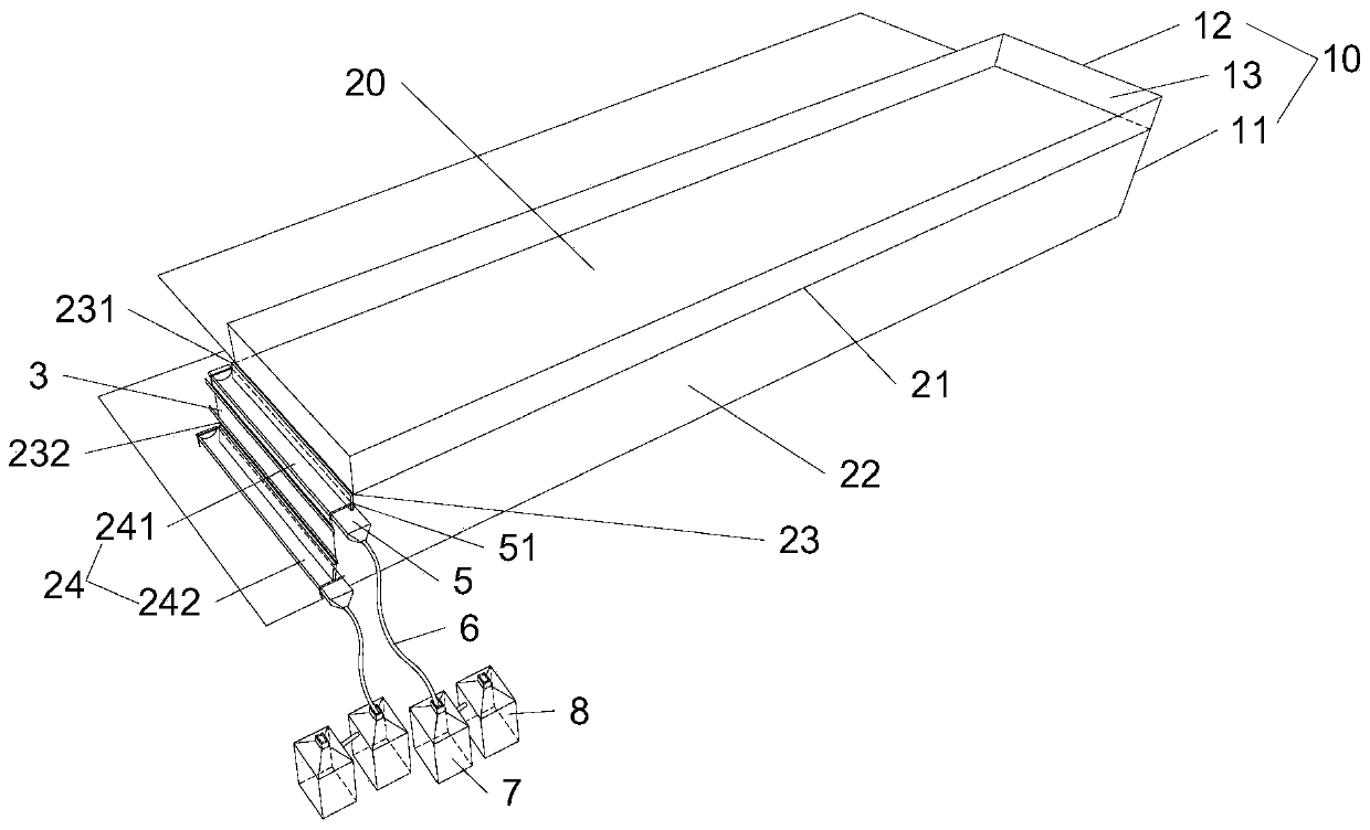
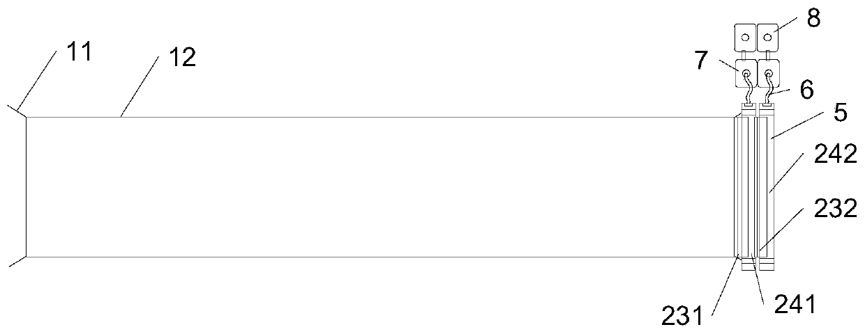
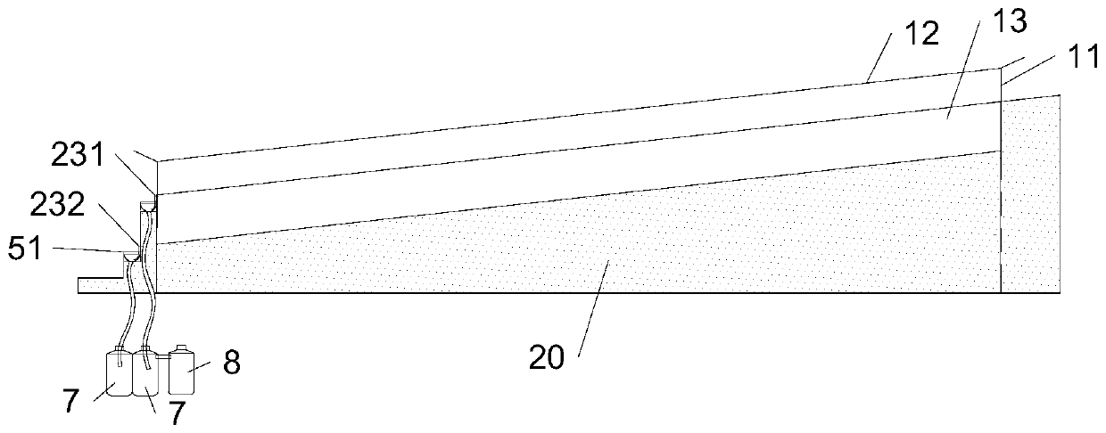
[0003] The purpose of the present invention is to provide a simple soil runoff observation area in the field to solve the technical problems of high construction cost of the observation area, large disturbance to the soil, and difficulty in repairing existing in the prior art

Method used


Image

  • Field simple soil runoff observation area
  • Field simple soil runoff observation area
  • Field simple soil runoff observation area

Examples


Embodiment 1

[0085] In Datong County, Xining City, Qinghai Province, a typical natural slope was selected for experiment and demonstration. The main steps are as follows:

[0086] (1) Select a natural slope with a length of 5m and a width of 1m along the slope, horizontal and vertical, with uniform slope and soil conditions;

[0087] (2) Excavate a 10cm wide and 30cm deep soil trench along the boundary of the protection ridge. Insert a stainless steel drill 11 with a width of 5mm, a thickness of 2mm and a length of 45cm into the four corners of the boundary of the plot vertically, with a depth of 20cm in the soil. The steel drill 11 is bent at 20 cm above the ground, and the iron wire 12 is fixed at the bent position.

[0088] (3) Use the iron wire 12 to enclose the small area along the steel drill 11 to form the side ridge structure frame.

[0089] (4) Cut the plastic sheet into a rectangle with a length of 11m and a width of 105m. Fold the plastic sheet in half along the wire 123 along the cente...


PUM

PropertyMeasurementUnit
diameteraaaaaaaaaa
thicknessaaaaaaaaaa

Abstract

The invention provides a field simple soil runoff observation area, and relates to the technical field of the environment monitoring device, and mainly aims at solving the technical problem that the traditional observation area is high in construction cost and hard to repair. The field simple soil runoff observation area comprises at least one observation unit isolated by an edge ridge and a groove; the edge ridge comprises enclosure plastic cloth, the observation unit is isolated from other soil body under the common action of the enclosure plastic cloth and the groove; the observation unit comprises a slope side soil matrix with an inclined upper surface, draining devices and collecting devices; a surface runoff layer and an interflow layer are orderly arranged on the slope side coil matrix from top to bottom; the draining devices comprise a surface runoff draining device and an interflow draining device; the collecting devices are located at a downward inclined side of the observation unit, and comprise the first collecting device and the second collecting device; the first collecting device is used for collecting the material drained from the surface runoff draining device, andthe second collecting device is mainly used for collecting the material drained from the interflow draining device.

Description

Technical field [0001] The invention relates to the technical field of soil erosion monitoring, in particular to a simple field soil runoff observation cell. Background technique [0002] Slope soil erosion is an important content of soil and water conservation monitoring and research. Runoff plots are a common method for observing the amount of soil erosion on slopes. It is the main method for studying the laws and mechanisms of soil erosion on the slope scale and evaluating the benefits of soil and water conservation measures. Small and medium-scale runoff plots have a small area, because their corresponding topography, soil characteristics, vegetation conditions, etc. are easier to grasp, so they are often used for control tests in the field of soil erosion. Runoff plots generally include protection belts, protection ridges, and protection ridges enclosed plots, water tanks, diversion pipes, water measuring facilities, drainage systems, etc. The common runoff plot specificatio...

Claims


Application Information

Patent Timeline
Patent Type & Authority Applications(China)
IPC IPC(8): G01N33/24
Inventor 贺康宁王冬梅刘若莎
Owner BEIJING FORESTRY UNIVERSITY
Why Eureka
Eureka Blog
Learn More