Optical projection system and device thereof

An optical projection and optical lens technology, applied in optics, optical components, instruments, etc., can solve the problems of less display information, viewing angle and aberration, virtual image enlargement, etc., and achieve the effect of expanding the imaging range, simple structure, and reducing aberration.

Inactive Publication Date: 2019-05-14
和全豐光電股ふん有限公司
View PDF12 Cites 0 Cited by
  • Summary
  • Abstract
  • Description
  • Claims
  • Application Information

AI Technical Summary

Problems solved by technology

Wherein, if the box body 91 of the head-up display is to project a two-dimensional image with a certain field of view (F.O.V), it must have a certain volume so that the two-dimensional image can be projected by the two optical mirrors 93 and 94. To the windshield 95, and this box body 91 should be set in the limited space in front of the driver's seat of the car. If you don't want to sacrifice the prospect of the car, it needs to be combined in the space in the instrument panel before the car leaves the factory, and because the light path is Vertically, the volume of the box body 91 is relatively thick, which makes its assembly very difficult
[0004] However, if you want to reduce the size of the head-up display or make the overall thinner, you will face three problems in optical design: virtual image magnification, viewing angle and aberration
When using a micro-projector or a liquid crystal display (LCD) as a display device, in order to realize a remote virtual image head-up display, it is necessary to cooperate with a rear-end virtual image magnification optical system (Relay Optics). However, the design of the virtual image magnification system is not easy and cannot be used The simplified optical structure effectively eliminates the aberration (Aberration) of large viewing angles, but the small viewing angle range will result in less display information, which limits the application efficiency of the head-up display; in addition, because the windshield is an irregular surface, it will cause reflections to the eyes , the deformation and aberration of the image, and it is very difficult to eliminate the deformation and aberration of the image. The mirror must be a large-area aspherical surface (Aspherical Surface), or another lens needs to be added to solve the aberration problem. This will increase the production cost of components and increase the difficulty of production and assembly
Therefore, the current penetration rate of installing head-up displays on cars has not been able to increase

Method used


Image

  • Optical projection system and device thereof
  • Optical projection system and device thereof
  • Optical projection system and device thereof

Examples


Embodiment Construction

[0044] In order to achieve the above-mentioned purpose and effect, the technical means and structure adopted by the present invention, the features and functions of the preferred embodiments of the present invention will be described in detail as follows in order to facilitate a complete understanding.

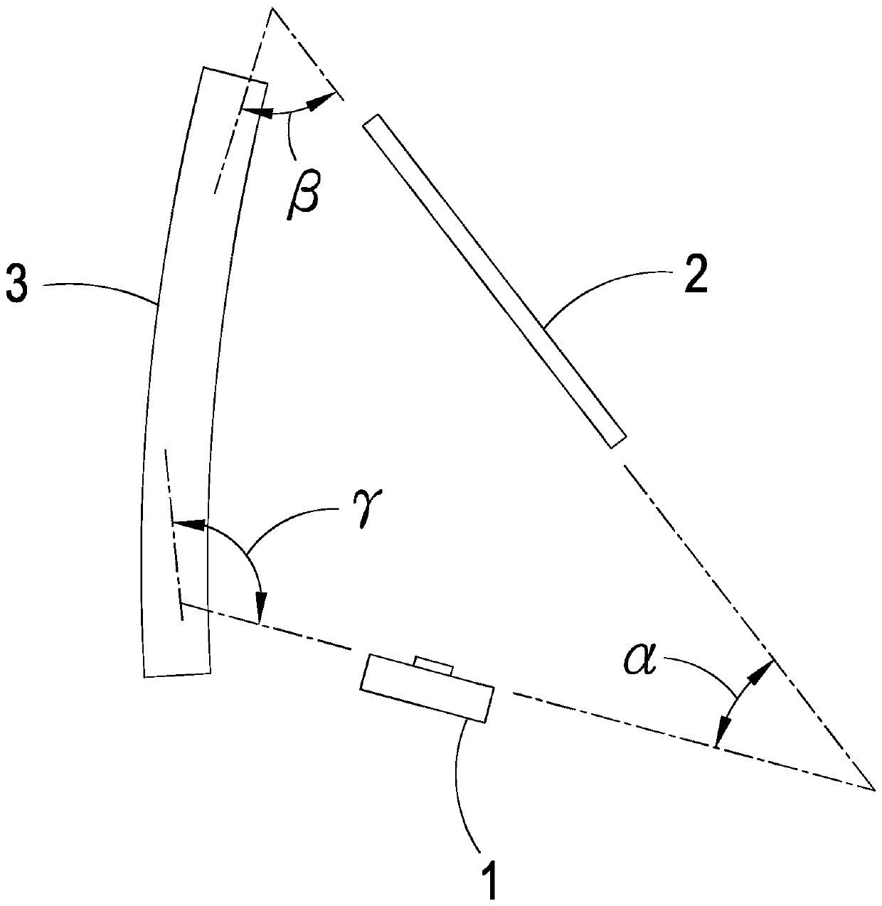
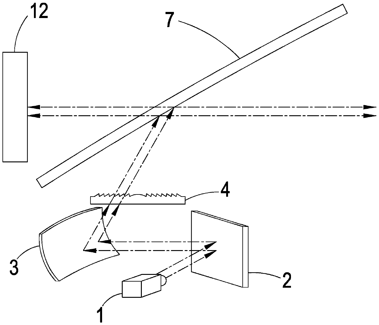
[0045] see figure 2 and image 3 As shown, it is a mirror position relationship diagram and a schematic diagram of an imaging path in a preferred embodiment of the present invention. It can be clearly seen from the figure that the optical projection system of the present invention includes:

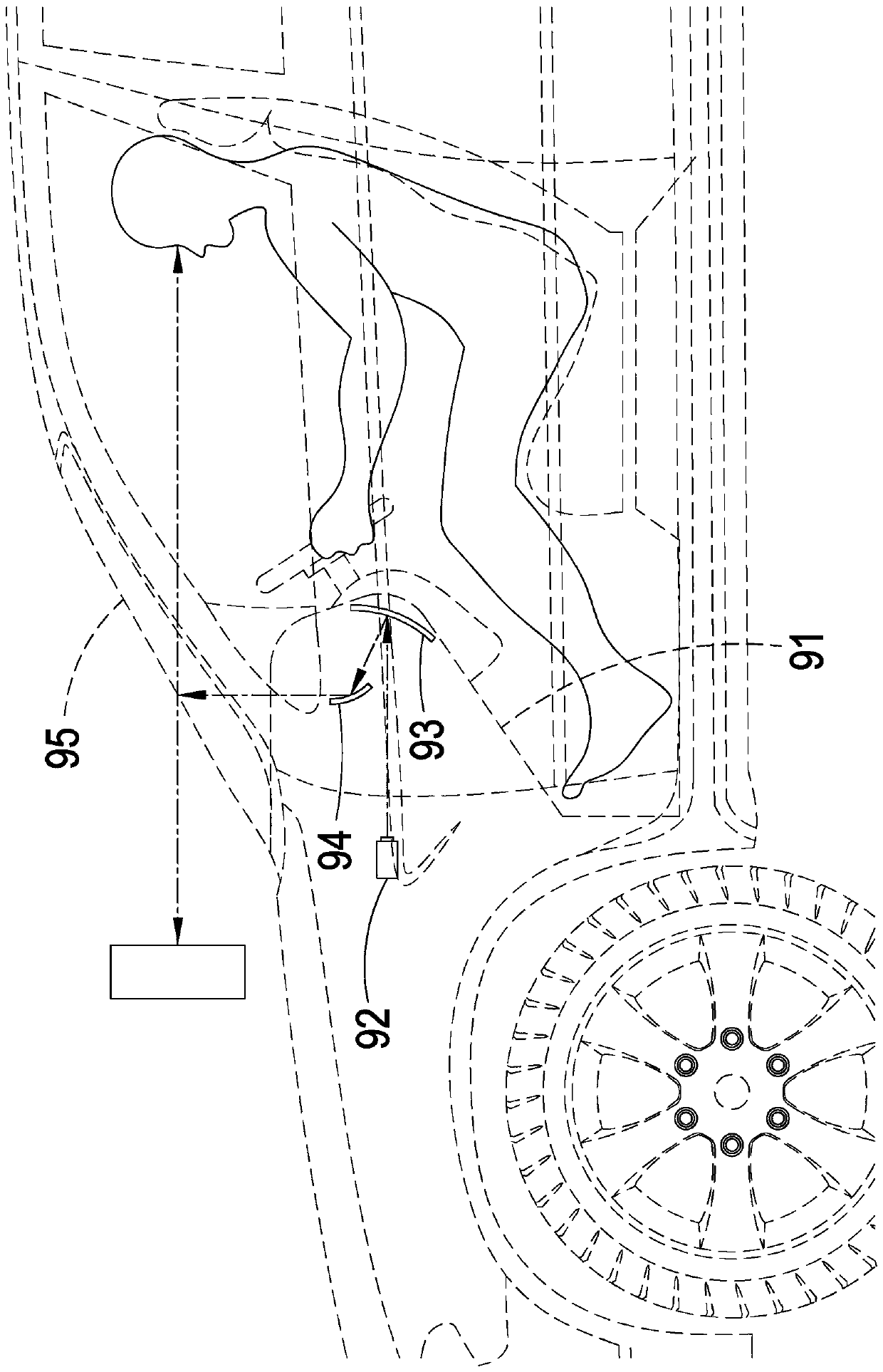
[0046] An imaging unit 1 for projecting at least one predetermined image 12;

[0047] a mirror 2 arranged on one side of the imaging unit 1 for receiving and reflecting the predetermined image 12;

[0048] A reflective curved mirror 3 located on one side of the imaging unit 1 and on the reflection path of the reflector 2 is used to adjust the imaging path and reduce virtual image aberr...


PUM


Abstract

The invention discloses an optical projection system and device thereof. A main structure of the optical projection system comprises an outer shell, at least one bonding part, and an optical projection system arranged in the outer shell; the optical projection system comprises an imaging unit, a reflector, a reflecting curved mirror, and at least one optical lens; a predetermined image projected by the imaging unit is projected to the reflecting curved mirror through the reflecting of the reflector, thereby adjusting an imaging path and reducing the aberration; the optical lens is used for amplifying the predetermined image in the path so that the predetermined image is reflected to eyes of a user through a windshield, and then a virtual image of the predetermined image is formed by refracting out of the windshield, therefore, the triangular imaging principle can be realized in a simple structure in the small space, the imaging range is enlarged, and the aberration problem is reduced,and the optical projection system can be simply assembled at the external of an instrument board through the outer shell.

Description

technical field [0001] The invention relates to an optical projection system and its device. Background technique [0002] Head Up Display (HUD) allows users to view the virtual image information projected by the HUD from the same angle of view while watching the scene ahead, without having to look down at the dashboard. This convenience and safety , that is, the car head-up display has gradually become a key to the modern trend. [0003] see figure 1 As shown, it is a schematic diagram of implementing a conventional head-up display. The head-up display includes a box body 91, inside the box body 91 there is a display device 92 that can emit image information, and through at least two optical mirrors 93, 94, the image information is emitted to the car windshield in front of the driver. 95. Make the virtual image of the image information appear after reflection, and be seen by the driver's eyes. Wherein, if the box body 91 of the head-up display is to project a two-dimens...

Claims


Application Information

Patent Timeline
Patent Type & Authority Applications(China)
IPC IPC(8): G02B27/01
Inventor 陈盈运
Owner 和全豐光電股ふん有限公司
Why Eureka
Try Eureka