Micro-channel jet radiator

A technology of tiny channels and heat sinks, which is applied in the direction of electric solid devices, semiconductor devices, semiconductor/solid device components, etc., can solve the problems of weakened injection effect, reduced injection effect, and reduced local heat dissipation coefficient, so as to ensure impact heat transfer Effect, enhanced heat dissipation effect, effect of ensuring independence

Active Publication Date: 2019-05-14
黄山市开发投资集团有限公司
View PDF13 Cites 13 Cited by
  • Summary
  • Abstract
  • Description
  • Claims
  • Application Information

AI Technical Summary

Problems solved by technology

However, on the one hand, since each jet beam ejected through the micro-nozzles of the baffle hits the upper wall of the injection chamber and then sputters away, it will negatively hinder the surrounding jets and weaken the jet impact of the surrounding jets. On the center line of two adjacent impacted surfaces, the fluid flow velocity is almost zero, and the local heat dissipation coefficient is sharply reduced; on the other hand, the liquid rebounded by the sprayed wall falls downward, weakening its own jet The injection force weakens the injection effect, and the fluid flowing out after the injection will flow through the nozzle at the outlet, which further weakens the jet injection force near the outlet of the micro-injector, greatly reducing the injection effect and limiting the heat transfer efficiency. promotion

Method used


Image

  • Micro-channel jet radiator
  • Micro-channel jet radiator
  • Micro-channel jet radiator

Examples


Embodiment Construction

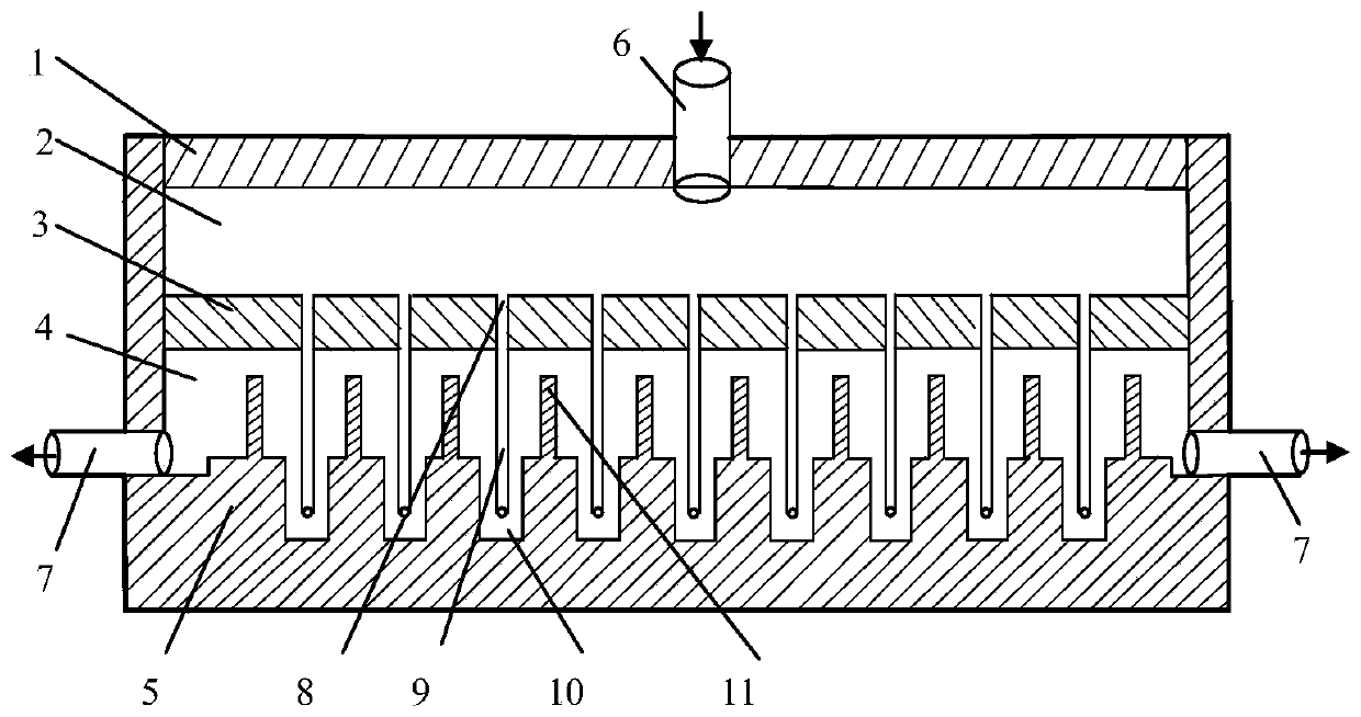
[0024] see figure 1 and figure 2 In this embodiment, the micro-channel jet radiator is provided with a cover plate 1 on the heat-conducting substrate 5 to form a box-shaped body with an inner cavity, and a partition 3 is horizontally arranged in the inner cavity, and the inner cavity is divided into an upper part by the partition 3 The liquid inlet chamber 2 and the lower liquid outlet chamber 4, the fluid working medium inlet 6 are arranged on the cover plate 1, and the fluid working medium outlet 7 are arranged on both sides of the heat conduction substrate 5; jet holes 8 are distributed on the partition 3.

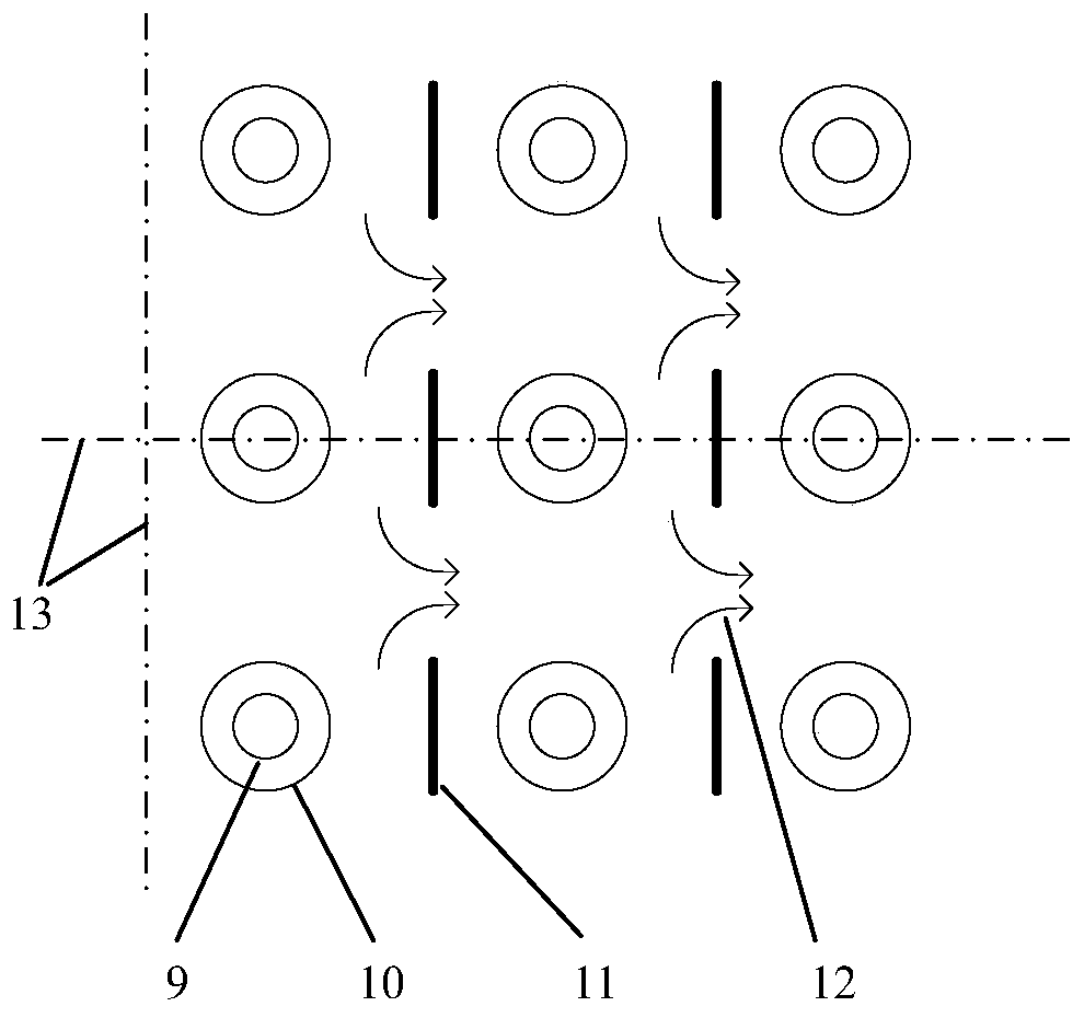
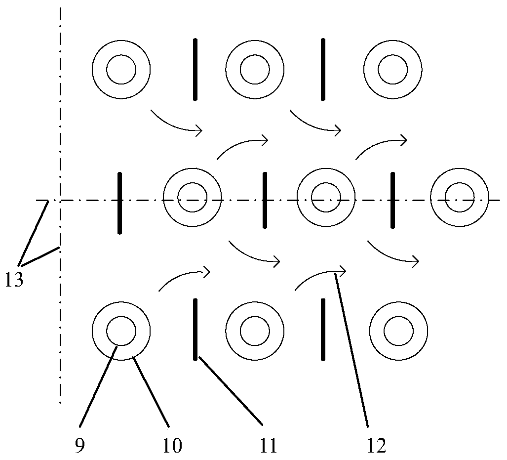
[0025] In the lower liquid outlet chamber 4, pits 10 are distributed on the surface of the heat-conducting substrate 5, and the pits 10 correspond to the jet holes 8 on the partition 3 in the vertical direction; Jet tube 9, the upper end surface of jet tube 9 is not higher than the upper surface of dividing plate 3, and the lower end of jet tube 9 hangs in the pit 10,...


PUM


Abstract

The invention discloses a micro-channel jet radiator. A cover plate is arranged on a heat conduction substrate to form a box-shaped body with an inner cavity; a partition plate is horizontally arranged in the inner cavity, and the inner cavity is divided into an upper liquid inlet cavity and a lower liquid outlet cavity; jet holes are distributed in the partition plate; pits are distributed in thelower liquid outlet cavity and located in the surface of the heat conduction substrate, and the pits are in one-to-one correspondence with jet holes in the partition plate; jet pipes are arranged inthe jet holes, and the lower ends of the jet pipes are suspended in the pits, so that the impact sputtering of the jet stream introduced by the jet pipes on the bottom surface of the pits is limited in the pits; in the lower liquid outlet cavity, rib sheets are distributed on the surface of the heat conduction substrate, and the rib sheets are arranged between the two adjacent pits in the workingmedium outflow direction, so that the working medium on the surface of the heat conduction substrate in the lower liquid outlet cavity is blocked from flowing through the downstream pits by virtue ofthe rib sheets. According to the radiator, the jet beam is not affected by the peripheral jet, and the sputtering jet is converted into positive disturbance to the heat conduction substrate, so that the heat exchange effect is enhanced.

Description

technical field [0001] The invention relates to the technical field of heat exchange of power electronic components, in particular to a micro-channel jet radiator. Background technique [0002] With the rapid development of highly integrated electronic devices, micro-electromechanical systems, and high-power lasers, electronic chips are developing in the direction of small size and high power, and the heat dissipation in the unit body is getting higher and higher, resulting in heat generation and temperature. A sharp rise, the heat flux has reached as high as 10 6 -10 7 W / m 2 , so that the temperature of the local hot spot exceeds its safety warning value in a very short period of time, which causes serious mechanical, chemical, electrical and other reliability and safety problems. Studies have shown that 30% of the failure of power electronic devices can be attributed to the thermal failure and thermal stress of the device. The higher the operating temperature of the dev...

Claims


Application Information

Patent Timeline
Patent Type & Authority Applications(China)
IPC IPC(8): H01L23/473
Inventor 唐志国张峰高钦程建萍
Owner 黄山市开发投资集团有限公司
Why Eureka
Try Eureka