
Ventilation cooling structure of fully-enclosed permanent-magnet motor

A permanent magnet motor, ventilation and cooling technology, applied in electrical components, electromechanical devices, electric components, etc., can solve the problems affecting the operation reliability of permanent magnet rotors, motor temperature rise, rotor structure damage, etc., and achieve a lightweight design. , The effect of strengthening heat dissipation and reducing the weight of the base

Inactive Publication Date: 2019-05-14
CSR ZHUZHOU ELECTRIC LOCOMOTIVE RES INST
View PDF1 Cites 4 Cited by
  • Summary
  • Abstract
  • Description
  • Claims
  • Application Information

AI Technical Summary

Problems solved by technology

This kind of ventilation and cooling structure has the problem that the turbulent flow in the ventilation channel is not obvious, and the heat taken away by the cooling air is limited, resulting in a high temperature rise of the motor and limited heat dissipation capacity.
At the same time, due to the adsorption characteristics of the permanent magnet of the rotor, iron powder and iron filings in the cooling air are easily adsorbed on the surface of the rotor, which can easily cause air gap blockage, rotor sweeping and other faults, causing damage to the rotor structure and affecting the operation of the permanent magnet rotor. reliability

Method used


Image

  • Ventilation cooling structure of fully-enclosed permanent-magnet motor
  • Ventilation cooling structure of fully-enclosed permanent-magnet motor

Examples


Embodiment Construction

[0016] In order to further explain the technical means and functions adopted by the present invention to achieve the intended invention purpose, the specific implementation, structure, features and functions of the present invention will be described in detail below in conjunction with the accompanying drawings and preferred embodiments.

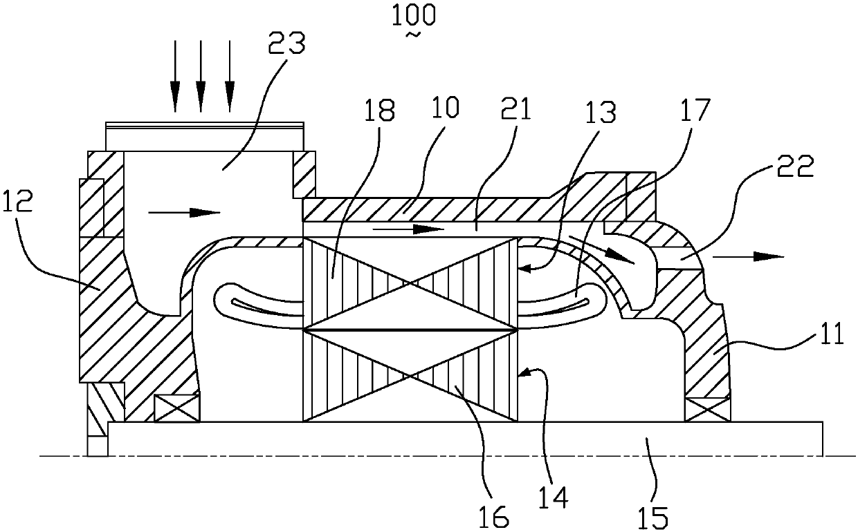
[0017] figure 1 It is a structural schematic diagram of the ventilation and cooling structure of the fully enclosed permanent magnet motor of the present invention. like figure 1 As shown, a fully enclosed permanent magnet motor ventilation cooling structure 100 includes a casing 10 , a front end cover 11 , a rear end cover 12 , a stator structure 13 , a rotor structure 14 and a pull plate 20 .

[0018] Wherein, the rotor structure 14 includes a rotating shaft 15 and a rotor core 16 , the rotor core 16 is fixedly assembled in the middle of the outer surface of the rotating shaft 15 , and the rotor core 16 is a cylindrical laminated core wit...


PUM


Abstract

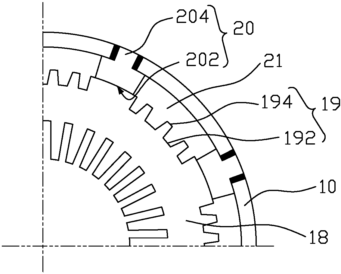
The invention proposes a ventilation cooling structure of a fully-enclosed permanent-magnet motor. The ventilation cooling structure comprises a shell, a front end cover, a rear end cover, a stator structure and a rotor structure, wherein the rotor structure comprises a rotation shaft and a rotor core, the rotor core is fixedly assembled at a middle part of an outer side surface of the rotation shaft, the stator structure comprises a stator core and a stator winding, the stator winding is wound around the stator core, a plurality of cooling fin structures are uniformly arranged on a peripheralsurface of the stator core, the stator structure also comprises a plurality of pull plates corresponding to the fin structures, the shell is of an arc structure with a plurality of segments, and thepull plates, the fin structures and the shell are sealed to form an axial ventilation passage penetrating through two ends of the shell. By arranging the cooling fin structures in the cooling ventilation passage, external air enters the cooling ventilation passage through a radial air inlet, larger and more obvious turbulence is generated by fin stirring, and more heat is taken away.

Description

technical field [0001] The invention relates to the technical field of motors, in particular to a fully enclosed ventilation and cooling structure for permanent magnet motors. Background technique [0002] A permanent magnet motor is a DC motor with a magnetic field established by one or more permanent magnets, which does not require electrical excitation of the rotor magnetic field. Since the permanent magnet has the characteristic of magnetically absorbing impurities easily, the motor needs to prevent foreign matter such as dust, water, acid and alkali from entering the interior of the motor and damaging the permanent magnet. Especially for permanent magnet motors for rail transit, in order to prevent the metal powder produced by the friction between the wheels and rails from entering the motor and adsorbing on the rotor surface of the permanent magnet motor when the rail vehicle is running, the air gap between the stator and rotor of the motor becomes smaller or even the ...

Claims


Application Information

Patent Timeline
IPC IPC(8): H02K5/20H02K5/18
Inventor 盛振强罗英露王健李伟业何思源李坤冯守智刘春秀刘雄
Owner CSR ZHUZHOU ELECTRIC LOCOMOTIVE RES INST
Learn More