
Handheld cleaning device

A cleaning device and hand-held technology, applied in cleaning equipment, suction filters, vacuum cleaners, etc., can solve the problems of increased hand heat, poor user experience, and the overall structure of the device is not compact enough, so as to improve convenience and reduce manufacturing costs. Effect

Inactive Publication Date: 2019-05-17
尚科宁家(香港)股份有限公司
View PDF10 Cites 0 Cited by
  • Summary
  • Abstract
  • Description
  • Claims
  • Application Information

AI Technical Summary

Problems solved by technology

[0004] However, the disposition of each component unit of the currently commercially available handheld vacuum cleaners is not compact enough, and the configuration of the weight distribution and the center of gravity is not reasonable enough, resulting in inconvenient adjustment of the direction of the hand in different cleaning directions. Poor user experience, not ergonomic
[0005] In order to improve the operation experience and convenience, make the product design more reasonable and tend to be perfect, various attempts have been made in the existing technology to try to make the overall structure of the device more reasonable, but there are always some unsatisfactory aspects, such as the United States The product structures disclosed in patented invention US 2017 / 0215663 A1 and Chinese patent CN 206934037 U both have the motor and the pre-motor filter coaxial and vertically arranged in front of the handle. When gripping, a large torque will be applied to the handle. In order to balance the weight distribution, the two existing technologies arrange the battery at the coaxial part with the handle (below the handle or respectively above and below the handle), and the arrangement of the battery close to the handle will inevitably increase the hand grip Heat sensation, not conducive to long-term operation, and not conducive to battery heat dissipation
Moreover, these two existing technologies respectively increase the length of the handheld vacuum cleaner in the horizontal direction and the vertical direction, and the overall structure of the device is still not compact enough, which is not conducive to storage.
[0006] Another example is the product structure disclosed in the US patent invention US 2018 / 0055315 A1. The motor is directly placed under the handle, the cyclone separation chamber and the motor are arranged horizontally, and the pre-motor filter unit is arranged between the two, which shortens the hand-held vacuum cleaner. The length in the horizontal direction, but because the battery is arranged under the motor, the weight under the handle is too concentrated, which also affects the operating experience
[0007] Therefore, the structure of the hand-held vacuum cleaner provided by the existing technology is difficult to achieve a balance between compact structure and reasonable weight distribution.

Method used


Image

  • Handheld cleaning device
  • Handheld cleaning device
  • Handheld cleaning device

Examples


Embodiment Construction

[0034] In order to explain the overall concept of the present invention more clearly, the following will be described in detail by way of examples in conjunction with the accompanying drawings.

[0035] In the following description, many specific details are set forth in order to fully understand the present invention. However, the present invention can also be implemented in other ways different from those described here. Therefore, the protection scope of the present invention is not limited by the specific details disclosed below. EXAMPLE LIMITATIONS.

[0036] In addition, in the description of the present invention, it should be understood that the terms "center", "upper", "lower", "front", "rear", "left", "right", "vertical", "horizontal" ", "Top", "Bottom", "Inner", "Outer", "Axial", "Radial", "Circumferential" and other indicated orientations or positional relationships are based on the orientations or positional relationships shown in the drawings , is only for the co...


PUM


Abstract

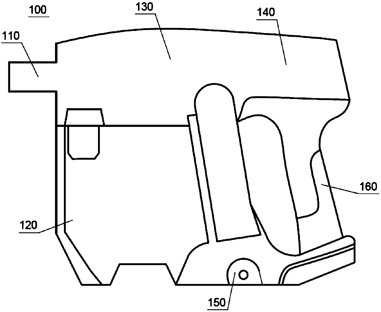
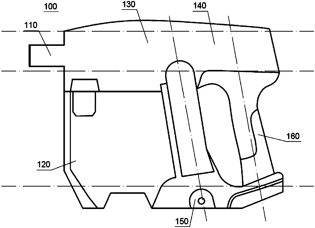
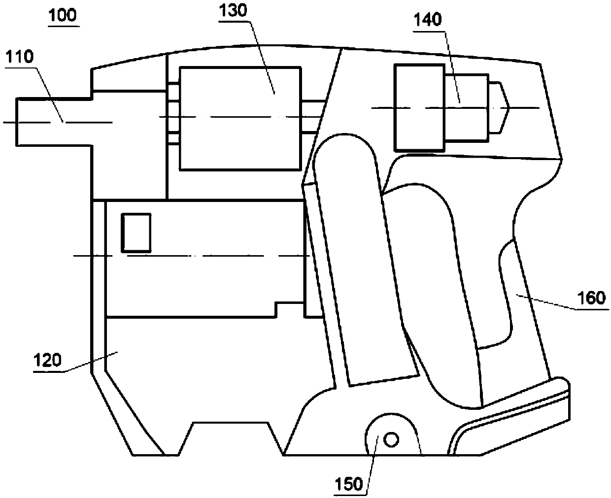
The invention provides a handheld cleaning device which comprises a host unit provided with an air inlet, a first-stage separation unit and an air flow generation unit, as well as a handle and an energy supply unit connected with the host unit, wherein the air inlet and the air flow generation unit are located in a first height region; the first-stage separation unit, the energy supply unit and the handle are located in a second height region; the first height region is located above the second height region. The handheld cleaning device can simultaneously meet the overall structural compactness the requirement and the weight distribution reasonability requirement, conforms to human engineering in structure and enhances the use experience of a user.

Description

technical field [0001] The invention relates to a hand-held cleaning device, which belongs to the field of vacuum cleaners. Background technique [0002] At present, various types of cleaning devices have been widely used in daily life. Common cleaning devices on the market, such as hand-held vacuum cleaners, are becoming more and more familiar to consumers. The mainstream choice when choosing a household vacuum cleaner. [0003] Hand-held vacuum cleaners generally use a cyclone-type separation chamber as the main separation unit to separate and screen debris and dust particles in the dirty air; an airflow generating device such as an electric fan is used to provide negative pressure as a power unit to drive the flow of dirty air; Then it is supplemented with auxiliary units such as a dirty air inlet pipe, a filter unit before the motor, an energy supply unit such as an energy storage battery, a filter unit after the motor, a connection structure that communicates or connec...

Claims


Application Information

Patent Timeline
IPC IPC(8): A47L5/24A47L9/16
Inventor 王旭宁
Owner 尚科宁家(香港)股份有限公司
Learn More