Low-energy artificial limb

A low-energy, prosthetic technology, used in prosthesis, medical science, artificial legs, etc., can solve the problems of poor comfort, inconvenient walking, and inconvenient wearing of prosthetics, reducing energy consumption, comfortable activities, and small size. Effect

Inactive Publication Date: 2019-05-17
JIANGSU UNIV OF TECH
View PDF9 Cites 1 Cited by
  • Summary
  • Abstract
  • Description
  • Claims
  • Application Information

AI Technical Summary

Problems solved by technology

[0003] The purpose of the present invention is to provide a low-energy prosthesis to solve the problems of poor comfort, inconvenient walking, inconvenient wearing and high energy consumption during work in the prior art.

Method used


Image

  • Low-energy artificial limb
  • Low-energy artificial limb
  • Low-energy artificial limb

Examples


Embodiment Construction

[0017] The following will clearly and completely describe the technical solutions in the embodiments of the present invention with reference to the accompanying drawings in the embodiments of the present invention. Obviously, the described embodiments are only some, not all, embodiments of the present invention. Based on the embodiments of the present invention, all other embodiments obtained by persons of ordinary skill in the art without making creative efforts belong to the protection scope of the present invention.

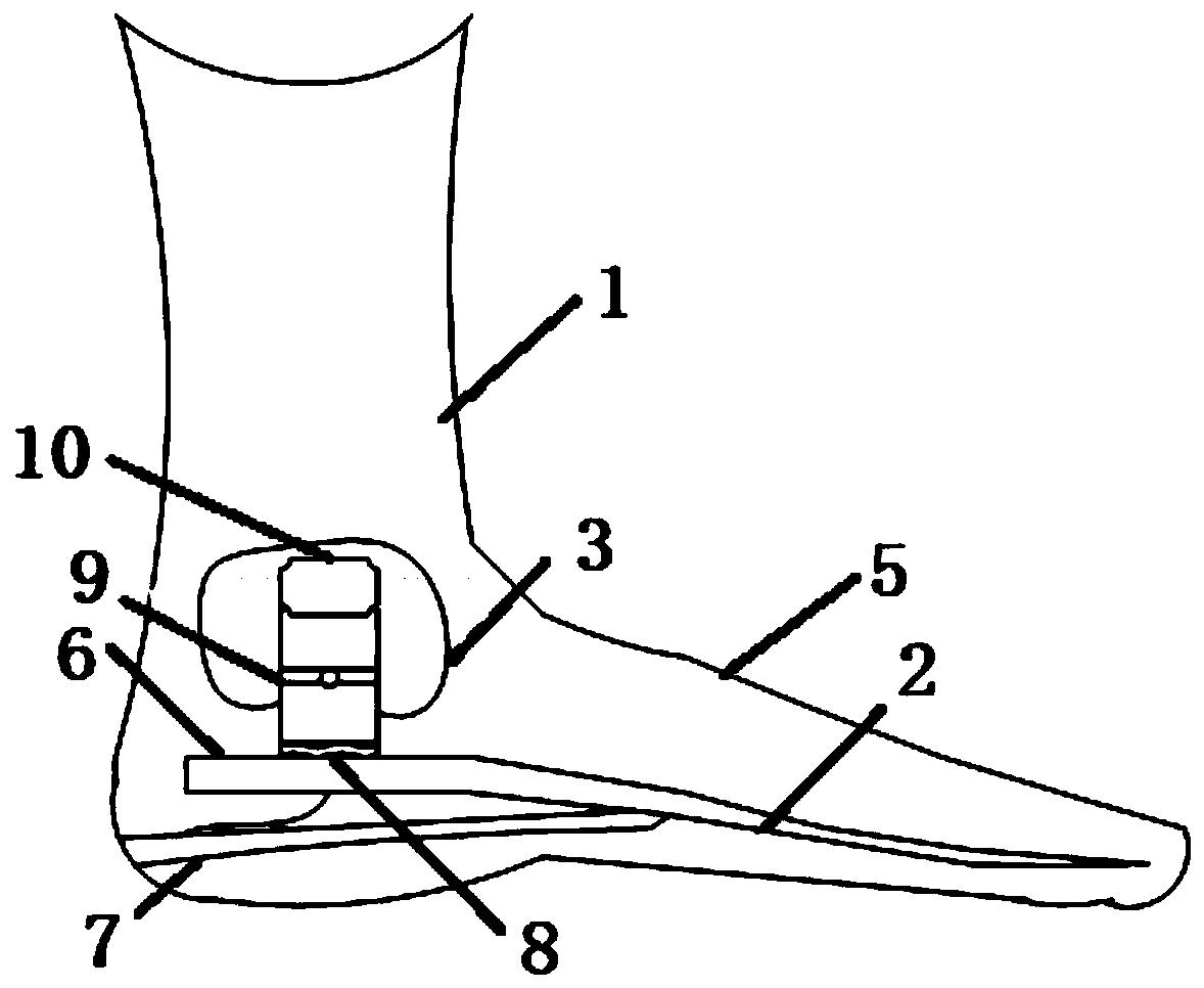
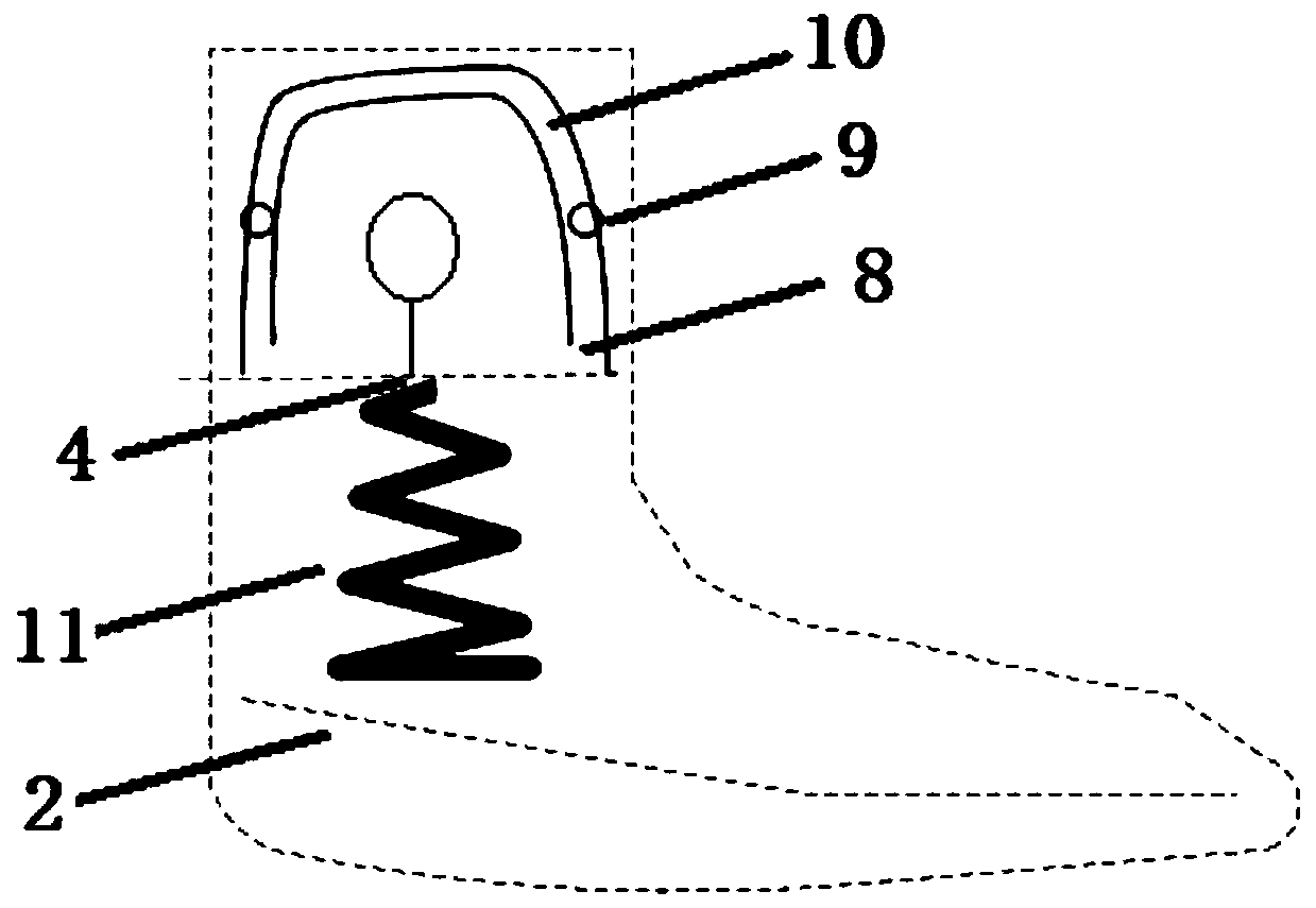
[0018] see Figure 1-2 , the present invention provides a technical solution: a low-energy prosthesis, including a calf prosthesis 1, an ankle joint 3 and a prosthetic foot plate 2, the ankle joint 3 includes two brackets 8 arranged on the rear top surface of the prosthesis foot plate 2, and the two brackets 8 are respectively Connect one side of a swing device 10 through a rotating shaft 9, the bottom of the swing device 10 is connected with the top of the pr...


PUM


Abstract

The invention relates to the technical field of medical care devices, in particular to a low-energy artificial limb comprising a calf artificial limb, an ankle joint and a prosthetic foot plate. The ankle joint comprises two brackets arranged on the top surface on the rear part of the prosthetic foot plate, the two brackets are connected on one side of a swinging device through a rotating shaft respectively, the bottom of the swinging device is connected to the top of the prosthetic foot plate by a spring, and the swinging device is internally provided with a charging conversion device. The charging conversion device converts kinetic energy generated during spring stretching into electric energy and stores the energy in a battery pack. The electric energy stored in the battery pack is usedfor driving the stretching of the spring when the prosthetic foot plate is raised. The low-energy artificial limb can solve the problem in the prior art that the existing artificial limb is poor in comfort, inconvenient to wear and high in energy consumption during work, and a user cannot walk conveniently by wearing the artificial limb.

Description

technical field [0001] The invention relates to the technical field of medical and health care equipment, in particular to a low-energy prosthesis. Background technique [0002] At present, there are many types of ankle joint prostheses on the market, mainly passive ankle joint prostheses, motor-driven active ankle joint prostheses, etc. The passive ankle joint prosthesis uses rubber, carbon fiber and other materials to make the foot plate, or introduces energy storage devices such as springs into the structure to make the whole foot have a certain elasticity. The passive ankle joint prosthesis has the advantages of simple structure, light weight, and low energy consumption. Passive ankle prostheses have no power source, and there is a problem that amputee walking does not match the trajectory of normal limbs; active ankle prostheses introduce active drive devices such as motors into the prosthesis structure. The main advantage of active ankle prostheses is that the wearer's...

Claims


Application Information

Patent Timeline
Patent Type & Authority Applications(China)
IPC IPC(8): A61F2/66A61F2/68
Inventor 王建华李垣江叶霞
Owner JIANGSU UNIV OF TECH
Why Eureka
Try Eureka